1.
2.
3.
Shut off the valve that is supplying air to transducer. It
is not necessary to remove the Transducer from
the air line.
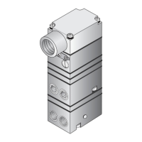
Remove the Orifice Assembly from the unit. For
detailed information see Figure 1 “T6000 Calibration
Configuration on page 1.
Clean with alcohol and dry with compressed air.
To clean the Orifice, use the following procedure:
MAINTENANCE
Parts must be completely dry before reas-
sembling.
If the standard maintenance procedure
does not correct the trouble, install Service
Kit EA-16798-1. (Sold Separately)
NOTES:
TROUBLE-SHOOTING
Table 1. Trouble-Shooting.
Problem
Solution (check)
Supply Pressure
Clogged Orifice
Input Signal
Pneumatic Connections
Zero and Span Adjust
Supply Pressure Low
Output Leakage
DC Signal
Loose Wires or Connections
Liquid in Air Supply
Dirt in Magnet Gap
No Output
Leakage
Low or Improper
Span Adjust
Erratic Operation
WARNING: Failure of Transducer could result in out-
put pressure increasing to supply pres-
sure possibly causing personal injury or
damage to equipment.
OM-50T6000S
Litho in USA
Rev. C 01/04
CALIBRATIONS / ADJUSTMENTS
Equipment Required for Calibration:
FULL RANGE OPERATION
Forward Acting Mode Adjustment
1.
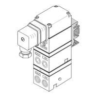
Connect the input signal to the transducer as shown
in the Installation Instructions, II-50T6000S.
Repeat steps 2-3 until the desired output range is
obtained. For detailed information, see Figure 1
“T6000 Calibration Configuration” on page 1.
• Pneumatic Supply capable of delivering up to 150 psig.
• Current Supply capable of delivering up to 60 mA.
• Pressure Gage capable of a digital readout up to 50 psig
with an accuracy of .1%.
• Digital Volt Meter capable of a readout up to 60 mA with
an accuracy of .02%.
4.
• Forward Acting Calibration-Zero
2.
Apply the minimum input signal and adjust the Zero
screw for minimum output pressure. Turn screw
clockwise to increase pressure and counterclock-
wise to decrease pressure.
Apply the maximum input signal and adjust the Span
screw for maximum output pressure. Turn screw
clockwise to increase pressure and counterclock-
wise to decrease pressure.
Reverse Acting Mode Adjustment
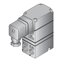
5.
Connect the input signal to the transducer as shown
in the Installation Instructions, II-50T6000S.
• Reverse Acting Calibration-Zero
6. Apply the minimum input signal and adjust the Zero
screw for maximum output pressure. Turn screw
clockwise to increase pressure and counterclock-
wise to decrease pressure.
• Forward Acting Calibration-Span
3.
8.
• Reverse Acting Calibration-Span
7.
Apply the maximum input signal and adjust the Span
screw for minimum output pressure. Turn screw
clockwise to decrease pressure and counterclock-
wise to increase pressure.
Repeat steps 6-7 until the desired output range is
obtained. For detailed information, see Figure 1
“T6000 Calibration Configuration” on page 1.
SPLIT RANGE OPERATION
All units have the capability to be split ranged or set for any
output in the range as long as the Output Span is equal to
or greater than the minimum Span.
The information set forth in the foregoing Operation
and Maintenance Instructions shall not be modified
or amended in any respect without prior written
consent of Fairchild Industrial Products Company.
In addition, the information set forth herein shall be
furnished with each product sold incorporating
Fairchild's unit as a component thereof.
LEGAL NOTICE:
INDUSTRIAL PRODUCTS COMPANY
3920 WEST POINT BLVD. WINSTON-SALEM, NC 27103-6708
TEL 336-659-3400
www.fairchildproducts.com
FAX 336-659-9323
R
ISO 9001:2000
FM NO. 25571
 Loading...