Do you have a question about the Fantek FT-6860 and is the answer not in the manual?
Warning symbol indicating risk of crushing or pinching.
General warning symbol for important information or caution.
Symbol indicating a correct procedure or state.
Symbol indicating an incorrect or prohibited procedure.
Symbol indicating a locked mechanism or state.
Symbol indicating an unlocked mechanism or state.
Warning symbol indicating electrical hazard.
Covers safe placement, leveling, stabilizer use, and load checks.
Emphasizes keeping clear of moving parts and proper load stability.
Covers inclined surfaces, mast order, stabilizer mounting, and load limits.
Includes load movement without leveling, mechanism lubrication, ladder use, and personnel lifting.
Covers load security, welding prohibition, power line clearance, and collision avoidance.
Covers outdoor use, wind effects, load clearance, and multi-tower lifts.
Emphasizes correct leveling and rules for mechanism/structural modes.
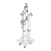
Diagram identifying all parts of the FT tower system.
Lifting load using winch, pulleys, and cables.
Lifting load using a manual hoist with the tower as a locked structure.
Step-by-step guide for lifting line arrays in mechanism mode.
Covers reinforcement bars, tower leveling, load weight calculation, and positioning.
Covers carrier brake release, load attachment, accessory securing, and mast raising.
Covers safety system status, section locking, and critical load descent procedures.
Fix and secure stabilizer legs to the base.
Turn forks and adjust to desired width, ensure with pins.
Covers stabilizer securing, fork adjustment, reinforcement bars, and load positioning.
Example calculation of load weight for line array accessories.
Covers carrier brake release, hoist attachment, accessory placement, and mast raising.
Covers safety system status, section locking, and raising the load with a hoist.
Covers hoist space, critical descent safety, and manual hoist descent.
Fix and secure stabilizer legs to the base.
Turn forks and adjust to desired width, ensure with pins.
Covers reinforcement bars, tower leveling, load calculation, and truss positioning.
Covers carrier brake release, truss attachment, accessory placement, and mast raising.
Covers safety system status, section locking, and critical load descent procedures.
Fix and secure stabilizer legs to the base.
Turn forks and adjust to desired width, ensure with pins.
Covers reinforcement bars, tower leveling, load calculation, and truss positioning.
Covers carrier brake release, truss attachment, accessory placement, and mast raising.
Covers safety system status, section locking, and critical load descent procedures.
Covers hoist space, critical descent safety, and manual hoist descent.
List of accessories available for the FT series towers.
Identification of various tower accessories.
Compatibility chart for accessories with different FT tower models.
Determine load position based on tower capacity and never exceed limits.
Table showing distances for load placement points (P1-P5).
Diagram illustrating load positions on the tower forks.
| Brand | Fantek |
|---|---|
| Model | FT-6860 |
| Category | Lifting Systems |
| Language | English |