Do you have a question about the Farmi Forest VALBY CH140 L and is the answer not in the manual?
Explains the 'Caution' symbol used for general safety reminders and unsafe practices.
Explains the 'Warning' symbol denoting specific potential hazards on the machine.
Explains the 'Danger' symbol indicating the most serious specific potential hazards.
Explains the 'Important' label for specific instructions to prevent machine damage.
Detailed safety precautions for operating the chipper, including personal protective equipment and work area safety.
Specific safety guidelines for using the hydraulic feeder and feed chute mechanisms.
Safety measures related to the hydraulic system, including oil handling and pressure.
Safety precautions when the chipper is powered by a separate hydraulic motor.
Instructions on how to properly park the chipper on a stable surface.
Essential steps to take before performing any lubrication or maintenance tasks.
General guidelines and warnings for lubricating the machine's components.
Detailed instructions on how to lubricate the machine's bearings.
Procedure for lubricating the PTO shaft at specified intervals.
Information on bearings, including replacement and clearance adjustment procedures.
Step-by-step guide on how to replace the bearings in the chipper.
Method for adjusting the radial clearance of the bearings using a feeler gauge.
Instructions for qualified personnel on how to replace the splined axle.
Information on maintaining the cutting components: knives and anvils.
Procedure for sharpening the chipper knives to ensure optimal performance.
Steps to adjust the gap between the knives and the anvil for efficient chipping.
Guidance on sharpening the anvil to maintain its effectiveness.
Instructions on checking and tightening the various bolts on the chipper.
Table detailing torque specifications and clearance measurements for key components.
Procedures for storing the chipper for longer periods to prevent damage.
Guidance on proper disposal of the machine at the end of its working life.
Describes the chipper's purpose, capacity, and intended use for processing wood waste.
Lists available optional accessories for the chipper, such as hydraulic feeds and adaptations.
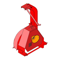
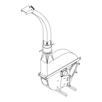
Identifies and labels the primary parts of the chipper with a diagram.
Lists the European and national standards the chipper complies with.
Provides detailed dimensions of the chipper through diagrams and measurements.
Instructions on how to position the chipper for safe transport on roads.
Safety guidelines and procedures for lifting the chipper unit correctly.
Step-by-step instructions for attaching the chipper to the tractor's 3-point hitch.
Guidance on installing an optional extension plate for improved stability.
Information regarding the Power Take-Off shaft, including type and maintenance.
Detailed procedure for shortening the PTO shaft to the correct length to prevent damage.
Crucial safety rules to follow during the operation of the chipper.
Steps to perform before starting the chipper, ensuring readiness and safety.
Instructions on how to safely start the chipper, including PTO engagement.
Guidelines and safety advice for the actual chipping process, including material feeding.
Tips for reducing power consumption, such as using fewer knives.
Steps to follow after finishing the chipping operation.
Method for clearing the chipper's internal components after use.
Specific procedure for safely shutting down the chipper when used with a tractor.
Procedure for safely shutting down the chipper when powered by a hydraulic motor.
| Brand | Farmi Forest |
|---|---|
| Model | VALBY CH140 L |
| Category | Chipper |
| Language | English |