6
Installation
Check that
the
voltage range
of
your TOPS
3D
is
suitable for the
local
mains supply. The instrument
is
normally supplied set
for
240V
+
10%,
any
alternative
voltage
is
marked
on
the
back
panel.
To
change
operat
ing
voltage
setting:
1. Disconnect unit from mains.
2.
Remove
4
screws
securing the
lower
edges
of
the
top
cover.
OPERATING
INSTRUCTIONS
3.
Remove 2 screws securing base
to
chassis.
4.
Remove
2
screws
securing
mains
protection
plate
to
chassis.
The
transformer taps are
now
visible.
For
110V
operation
link
0
to
0
and
110
to
110V.
Indicate
new
setting
with
suitable
label
on
the
back
panel.
The
three
core mains lead must be connected as follows:
Brown
Blue
Green /
yellow
WARNING
Mains
live
Operation
Mains
neutral
Safety earth (ground)
The safety earth must be connected at
all
times.
The
unit
is
cooled
by
natural
convection
and
on
no
account
should
airflow around the unit
be
restricted. The heatsinks at the rear
of
the
units
must
not
be
touched
as
they
can
attain
high
temp
eratures.
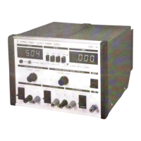
Move
'input'
switch
to
'on' the
led
digits illuminate
and
the
power
supply
is
ready
for
use.
Any
one
of
the
three
outputs
can be simultaneously monitored
on
voltage and current
by
depressing the appropriate 'meter'
push
button.
To
minimise digit flickering
on
the current meter
when
monit
oring rapidiy varying currents, an increased time constant
can
be switched
in
by
depressing
the
'current meter damping' push
button.
By
releasing
all
three output select
push
buttons the voltmeter
can
be
used
to
measure
external
voltages
via
the
front
panel
sockets.
In
this mode
the
DVM
is
isolated from any
of
the
power
supply
outputs
and
is
able
to
be
floated
up
to
200
V
dc
or
ac
peak
from
earth. The maximum reading
is
39.99
volts.
 Loading...