Do you have a question about the Farris Engineering 2700 Series and is the answer not in the manual?
Explains the meaning and use of safety labels like DANGER, WARNING, CAUTION, and NOTICE.
Provides guidance for handling, storage, and installation of Farris valves, emphasizing safety.
Details critical safety precautions for DANGER, WARNING, and CAUTION conditions during valve operation and servicing.
States the purpose of the manual to ensure proper installation, repair, and safe operation of Farris pressure relief valves.
Outlines steps for inspecting valves upon receipt, checking for damage, and proper storage conditions.
Details the importance and procedures for set pressure and seat leakage testing before installation.
Provides essential guidelines for proper valve installation to ensure performance and safe operation.
Illustrates typical pressure relief valve installations with and without shutoff valves.
Covers fundamental maintenance procedures applicable to all Farris valve series.
Details set pressure calibration and testing procedures, including fluid selection and leakage testing.
Diagram illustrating the components of the Farris 2600 Series BalanSeal® Bellows Safety Valve.
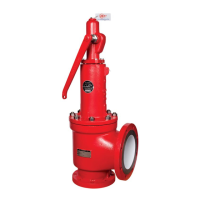
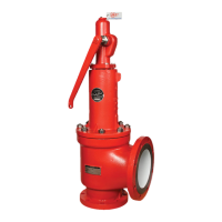
Diagram showing the components and internal structure of the Farris 2700 Series valve.
Diagrams illustrating the main valve, snap-acting control, and modulating control for the 3800 Series.
Diagrams of the Farris 4200 and 6400 Series Steam Valves, highlighting key components.
Diagrams of the Farris 1890/1896 and 2850/2856 Series valves, showing internal components.
Details Farris's global FAST Center Network for valve services, emphasizing responsiveness and experience.
Outlines aftermarket services including valve expertise, factory-trained technicians, and OEM parts usage.
| Brand | Farris Engineering |
|---|---|
| Model | 2700 Series |
| Category | Control Unit |
| Language | English |