4
Support to resist weight
and reaction forces
Cap may be required for
weather protection
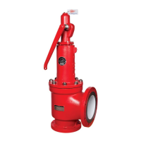
Recommended Typical Pressure Relief
Valve Installation Without Shutoff Valve
If connected to a closed system,
specific care should be taken to
keep piping strains away from
the pressure relief valve under all
conditions of process operation.
Pressure
relief valve
Pressure drop
not more than
3% of set
pressure
Body drain
Long radius elbow
Vessel
Support to resist weight
and reaction forces
Cap may be required for
weather protection
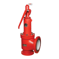
Recommended Typical Pressure Relief
Valve Installation With Shutoff Valve
If connected to a closed system,
specific care should be taken to
keep piping strains away from
the pressure relief valve under all
conditions of process operation.
Pressure
relief valve
Pressure
drop not
more than
3% of set
pressure
Body
drain
Long radius elbow
Vessel
Stop valve preferably should have full round
port area and be equal to or greater than the
inlet size of the pressure relief valve. This stop
valve should be used only as permitted in the
applicable codes.
Figure 1.1 Figure 1.2
Install valves away from equipment that may cause turbulence, such as
reducing stations, orifice plates/nozzles, and other valves and fittings.
Make sure all inlet and outlet piping is properly supported to avoid
putting excessive load on the valve. Provide drainage from the
discharge piping or valve body.
On valves with bellows, remove plastic shipping plugs from the bonnet
and vent in a safe direction. Do not pipe bonnet vents to a pressurized
system that would introduce backpressure.
Clean inlet and outlet flange surfaces and valve interior cavity to remove
rust inhibitors.
Remove the inlet and outlet flange protectors and any extraneous
packing or documentation materials inside the valve body or nozzle.
Test levers are provided on some valves to allow the user to manually
verify that the valve trim is free to move. Test levers should only be
pulled when system pressure is greater than 75% of set pressure in
order to avoid potential damage to the valve. In addition the valve
should never be carried by the test lever as this can move the disc
off the seat resulting in damage to both parts.
Tighten all inlet and outlet flange bolts evenly. Leave enough room
to allow for in-line maintenance and adjustments.
Additional Instructions for Pilot Valve:
Pilot valves are equipped with bug vent(s) on the pilot control bonnet
and/or body. Check to be sure vents have not been plugged.
The pilot control discharge is vented to atmosphere since the volume
released when the valve opens is small. If a release to atmosphere is not
permitted, then vent the discharge to a safe location. Do not pipe discharge
to a pressurized system that would introduce backpressure unless it is a
balanced pilot control design.
On pilot valves supplied with field test connections, remove the plastic
shipping plug from the isolation valve and assure that it is partially open.
System Start Up and Testing:
It is recommended that the valve be isolated during
pressure testing of the system either by blanking,
closing a stop valve or using a test tag. If a test
gag is used, exercise extreme caution to avoid
damaging the valve stem or seat by over tightening
the gag screw. Gag screws should be installed hand
tight and should always be removed after system
testing has been completed. Remove the optional
test gag, if supplied.
Typical PRV Installation
API RP 520, Part II Installation
Valve will not function
with test gag in place.
NOTICE