Advanced Function Instruction
7-3
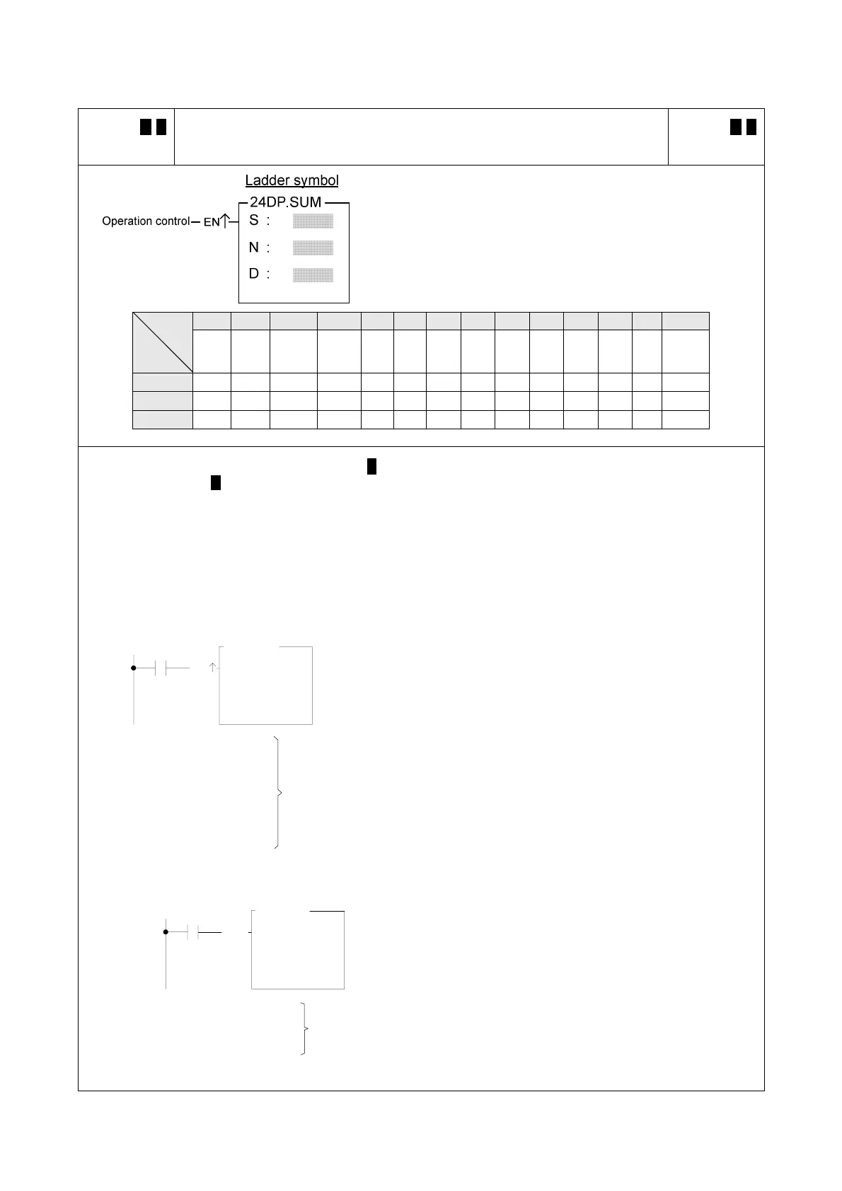
FUN 24 D P
SUM
SUM
(Summation of block data)
FUN 24 D P
SUM
S : Starting number of source register
N : Number of registers to be summed
(successive N data units starting from S)
D : The register which stored the result (summation)
S, N, D, can associate with V, Z, P0~P9 index register to
serve the indirect addressing application.
WX WY WM WS TMR CTR HR IR OR SR ROR DR K XR
Range
Ope-
rand
WX0
∣
WX240
WY0
∣
WY240
WM0
∣
WM1896
WS0
∣
WS984
T0
∣
T255
C0
∣
C255
R0
∣
R3839
R3840
∣
R3903
R3904
∣
R3967
R3968
∣
R4167
R5000
∣
R8071
D0
∣
D4095
1
∣
511
V、Z
P0~P9
S ○ ○ ○ ○ ○ ○ ○ ○ ○ ○ ○ ○ ○
N ○ ○ ○ ○ ○ ○ ○ ○ ○ ○ ○ ○ ○ ○
D ○ ○ ○ ○ ○ ○ ○ ○* ○* ○ ○
z When operation control “EN”=1 or “EN↑” ( P instruction) changes from 0→1, it puts the successive N units of
16bit or 32 bit ( D instruction) registers for addition calculation to get the summation, and stores the result into
the register which is designated by D.
z When the value of N is 0 or greater than 511, the operation will not be performed.
z Communication port1 or port2 can be used to serve as a general purpose ASCII communication interface. If
the data error detecting method is Check-Sum, this instruction can be used to generate the sum value for
sending data or ot use this instruction to check if the received data is error or not.
〈Example 1〉When M1 changes from OFF→ON, following instruction will calculates the summation for 16-bit data.
M1
EN
S :
N :
D :
R0
6
R100
24P.SUM
z The left illustrates that 6 16-bit registers starting from R0
is calculated for summation, and the result is stored into
the R100 register.
R0=0030H
R1=0031H
R2=0032H
R3=0033H
R4=0034H
R5=0035H
〈Example 2〉When M1 is ON, it calculates the summation for 32-bit data.
S :
N :
D :
R0
3
R100
24D.SUM
EN
M1
z The left illustrates that three 32-bit registers starting
from DR0, is calculated for their summation, and the
result is stored into the DR100 register.
R1,R0=00310030H
R3,R2=00330032H Î R101,R100=00A5009BH
R5,R4=00410039H
Î R100=012FH