Advanced Function Instruction
7-114
FUN 139
HSPWM
HIGH SPEED PULSE WIDTH MODULATION OUTPUT
FUN 139
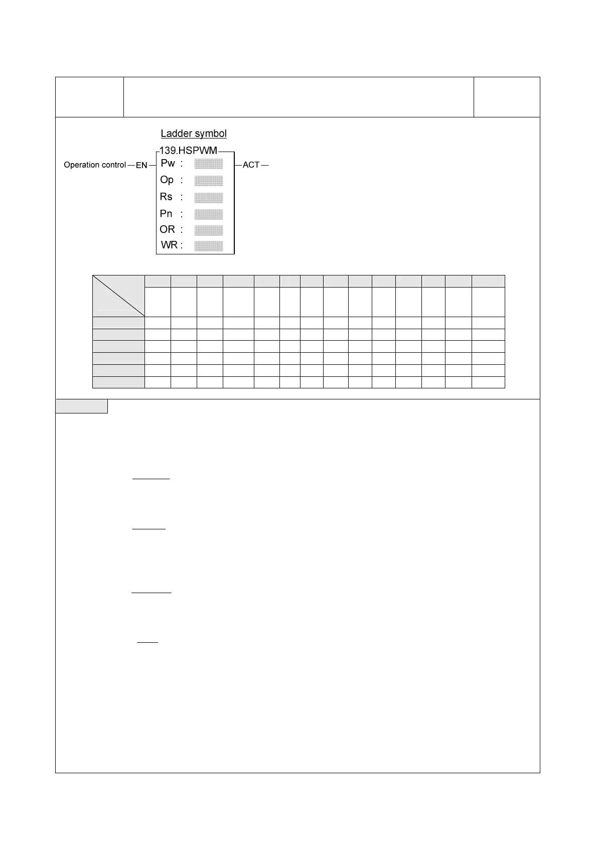
HSPWM
PW : PWM output ( 0 = Y0、1 = Y2、2 = Y4、3 = Y6 )
OP : Output polarity ; 0 = Normal
1 = Inverse of output
RS : Resolution ; 0 = 1/100 (1%)
1 = 1/1000 (0.1%)
Pn : Setting of output frequency( 0~255 )
OR : Setting register of output pulse width ( 0~100 or
0~1000)
WR : Working register
Y WX WY WM WS TMR CTR HR IR OR SR ROR DR K
Range
Operand
Yn of
main
unit
WX0
∣
WX240
WY0
∣
WY240
WM0
∣
WM1896
WS0
∣
WS984
T0
∣
T255
C0
∣
C255
R0
∣
R3839
R3840
∣
R3903
R3904
∣
R3967
R3968
∣
R4167
R5000
∣
R8071
D0
∣
D4095
Pw ○ 0~3
Op 0~1
Rs 0~1
Pn ○ ○ ○ ○ ○ ○ ○ ○ ○ ○ ○ ○ 0~255
OR ○ ○ ○ 0~1000
WR ○ ○ ○ ○ ○ ○ ○ ○ ○ ○
Description
z When operation control “EN” = 1, the specified digital output will perform the PWM output, the expression for
output frequency as shown bellow:
1.
)1+P(
184320
=f
n
pwm
while Rs(Resolution)=1/100
2.
)1+P(
18432
=f
n
pwm
while Rs(Resolution)=1/1000
Example 1 : If Pn ( Setting of output frequency ) = 50, Rs = 0( 1/100 ), then
)1+50(
184320
=f
pwm
=3614.117‧‧‧ ≒3.6KHz
T(Period)=
pwm
f
1
≒277uS
For Rs = 1/100, if OR( Setting of output pulse width ) = 1, then T0 2.7≒ uS; if OR( Setting of output pulse width )
= 50, then To ≒ 140uS.
.Output waveform :
(1).Pn ( Output frequency ) = 50, Rs = 0 ( 1/100 ), OR ( Output pulse width ) = 1 :