H3-2
main unit. Users can easily find each terminal with its I/O number and LED status indication, as shown in the figure
below using X10 and Y6 as an example:
OUT Y
( )
Y6Y1
AC100~240V
C0
Y0
Y4
Y2
C2
Y3
PORT0
Y5
C4 C6
Y8
Y7 Y9
SINK
SRCE
( )
IN X
X8X0
PROGRAMMABLE
CONTROLLER
24V OUT
S/S
RXTX
RUN
ERR
POW
X4X2
X1 X3
X6
X5 X7
X12X10
X9
X11 X13
X10
Y6
max.
400mA
IN
0
I
23
7654
I0 I I
98
I3I2
0
4
8
9
56
2
I 3
7
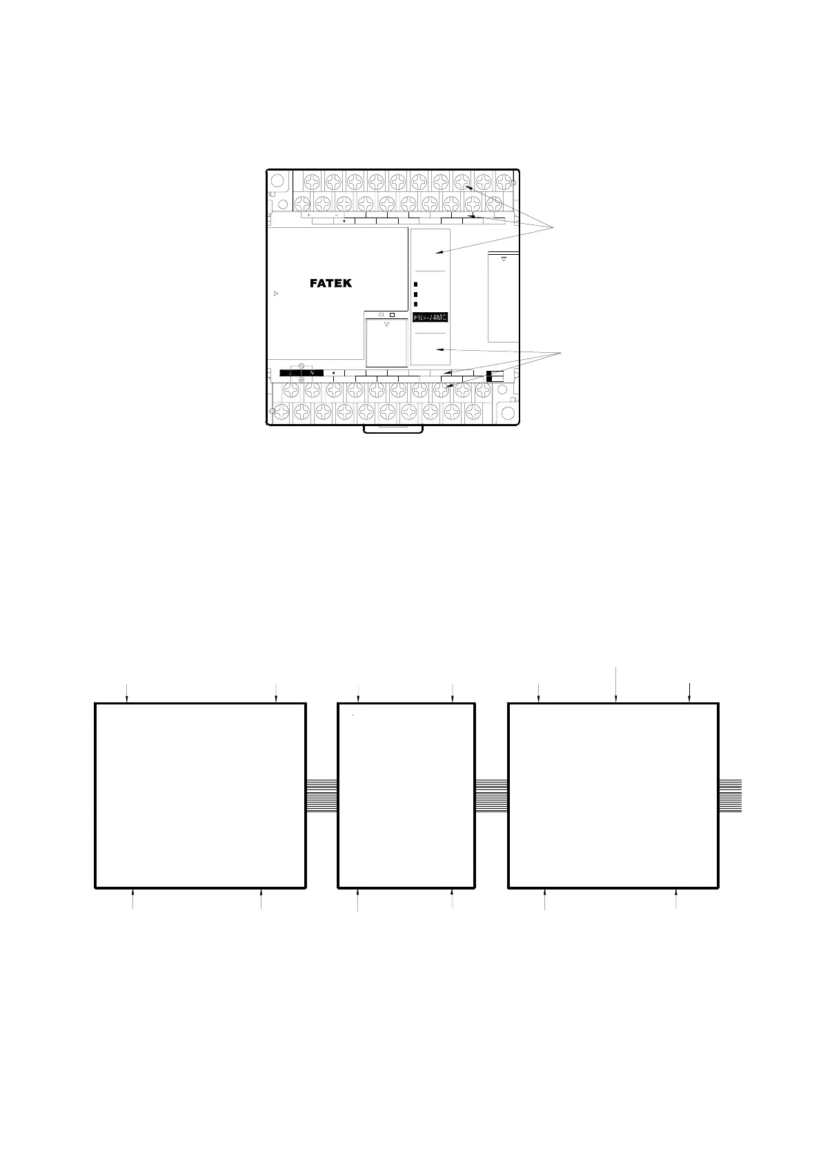
While the various expansion units/modules other than the main units have the same printed labels on the input/output
terminals as the main units do, these labels are only relative I/O numbers, different from the absolute I/O numbers on
main units. The number of a terminal only represents its order on the expansion unit/module. For example, the first
contact is X1 or Y1, the second X2 or Y2, etc. All numbers on the expansion unit/module begin with 1. The actual
number of digital input contact or the output replay, however, is determined by summing the numbers on all previous
expansion units/modules and the main unit. See the following figure and its calculation.
X0
X23
X24
X37
X38
X61
X49
Y0
Y15
Y16
Y25
Y26
Y41
FBS-40M△
FBS-24EA
FB
S-40EAP
(
主機 )
(
第1個擴充機/模組 )
(
第2個擴充機/模組 )
Y0 Y1 • • • • • • • • • • • • Y15
X0 X1
• • • • • • • • • • • • • • X23
X1 X2
• • • • • • • • X14
Y1 Y2
• • • • • • • • Y10
X1 X2
• • • • • • X12 • • • • • • X24
Y1 Y2
• • • • • • • • • • • • Y16
As shown in the above figure, because the top X numbers of the previous two units are 23 and 14, respectively, the
number of input contact X12 on second expansion unit should be:
X (23+14+12) = X49
Main Unit
1
st
expansion
unit/module
2
nd
expansion
unit/module