H5-3
Model
Item
POW-10-D POW-16-D FBS-EPOW-D
Rated Voltage 24VAC -15% / 20%
Max. Power Consumption 15W 24W 15W
Inrush Current 20A@24VDC
Allowable Power Interrupt 20ms(min.)
Fuse Spec.
3A,250VAC
Isolation Type Transformer/Photo Coupler Isolation, 500VDC/minute
5VDC(logic circuit) N/A*
2
5V,±5%,1A(max) 5V,±5%,0.4A(max)
24VDC(output circuit)
24V±10%,200mA(max)*
3
24V,±10%,400mA(max) 24V,±10%,250mA(max)
Power*
1
Output
24VDC(input circuit)
Directly from input power, but limited by specifications of circuit and fuses, with
capacity of 400mA(max.)
Note *
1
:The 5VDC (for logic circuit) output power and the 24VDC (for output circuit) power can be accessed from the “I/O expansion
output header” located on the right side of main/expansion units for expansion modules. The 24VDC power for input circuit
is provided from the farthest 2 upper left terminals (labeled “+24V OUT-”) on the input terminal block of main/expansion unit
to input circuit in expansion module or other sensors.
Note *
2
:The 5VDC power of 10/14PTs main unit is generated by the oscillations of the 24VDC power in the output circuit, with
specifications of 5VDC±10% and 400mA (max) (Circuit is located on the I/O board of 10/14PTs main unit)
Note *
3
:Without any I/O expansion interface, the 24VDC power in 10/14PTs main unit is for its output circuit alone and cannot be
used for other purposes.
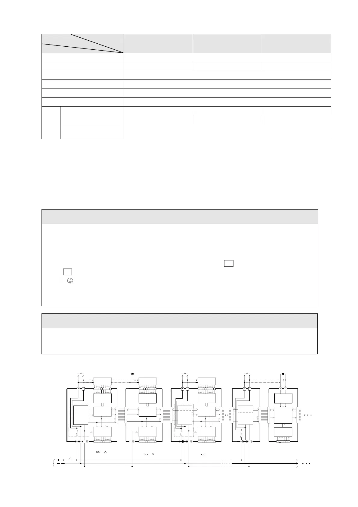
Note
The schematic diagram of DC power supply in main/expansion unit is shown below. Also be cautious about the
following:
Please follow the wiring schemes regulated by local national standards to choose single-pole switch (break
24V+) or double-pole switch (break both 24V+ and 24V
−
) in order to turn on or off DC input power.
Wiring of 24V+ input power must be connected to the terminal labeled by + , while the 24V
− end is connected
to the
– terminal, Please use wires with diameters of 1mm
2
~2mm
2.
The G terminals on main unit and all digital expansion units/modules must be connected to the EG (Earth
Ground) terminal on main power system according to the scheme shown in the following figure, using wire
diameters larger than 2mm
2
.
Warning
Output of 24VDC power for input circuit cannot be connected in parallel with other powers, in which the conflict
between two sets of power will decrease their lifetime or cause immediate damage. This will induce unexpected
malfunction of PLC and cause serious or even deadly damage to people or equipment.
Expansion unit
(FB
S- EAP-D)
24V
0V
Output
24VDC
power
SW
F
Output
F
CPU
Input
POW-16-D
DC-DC
Power
Supply
0V
24V
5V
OUT
Main unit
(FB
S- M -D)
control
Input
POW -16-D
OUT
Expansion module
(FB
S- E )
Output
F
AI
(FB
S-6AD, 2DA,
TC6,RTD6...)
Expansion module
control
CONVERTER
(DC-DC)
Input
control
0V
24V
OUT
Expansion
power supply
(FB
S-EPOW-D)
IN
5V
DC-DC
Power
Supply
DC-DC
Power
Supply
24VDC output
(for input)
24VDC
external power
input /
Sensor
OR
input /
Sensor
24VDC output
(for input)
input /
Sensor
24VDC
external power
24VDC output
(for input)
OR
S
ec.