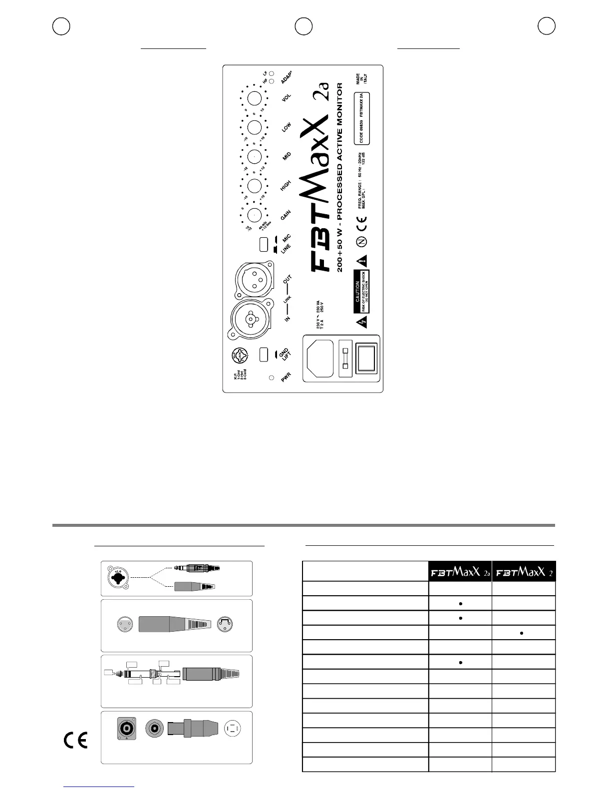
CONNESSIONI/CONNECTIONS SPECIFICHETECNICHE/TECHNICALSPECIFICATIONS
CONTROLLI CONTROLS
12
21
33
LatosaldatureLatocontatti
1.Massa2.Fase+3.Fase-Schermo(Shield)Caldo(Hot)Freddo(Cold)
XLR
*SPEAKONèunmarchioregistratoNEUTRIK *SPEAKONisaregistredtrademarkofNEUTRIK
1+ PositivePositivo/
1- NegativeNegativo/
Speakon*
PresaSpeakon
1+
2+
2- 1-
XLR-F(micro)
1=SHIELD
2=HOT
3=COLD
LINE
JACK
12
3
NEUTRIKXLR/JACK-COMBO
Jackstereo/bilanciato/balanced
TIP=Positive(+orhot)
SLEEVE=Shieldorground
RING=Negative(-orcold)
TIP
TIP
RING
RING
SLEEVE
SLEEVE
I UK
Configurazione
Type
22
200+50
4/8
250
50Hz-20kHz50Hz-20kHz
500
9797
121/124121
1x2501x250
25.4+tromba 25.4+tromba
25.4+horn 25.4+horn
352x550x307
352x550x307
10
13
2xspeakonXLR-Jack
Impedenzanominale
Nominalimpedance
Amplificatoreraccomandato
Recommendedamp.
Amplificatoreinterno
Built-inamplifier
Wrms
Wrms
@-5dB
(IEC268-5)Wrms
@1W/1mdB
dB
mm
mm
(LxAxP)mm
(WxHxD)mm
kg.
vie/way
ohm
Rispostainfrequenza
Frequencyresponse
Shortterm
Shortterm
Sensibilità
Sensitivity
MassimoSPL
MaximumSPL
Unitàbassefrequenze
Unitàaltefrequenze
Lowfrequencywoofer
Highfrequencydriver
Dimensioni
Dimensions
Peso
Weight
Connettoridiingresso
Inputconnectors
#IN-link-OUT
#GAIN
#HIGH/MID/LOW
#VOL
#GNDLIFT
.
A.D.A.P
PWR:
:Presediingressoeduscita
bilanciateelettronicamente.Lapresa“IN”
XRL+Jack-Combo-consenteilcollegamentodiun
microfonodinamicoabassaimpedenzaoun
segnalepreamplificatocomequelloinuscitadaun
mixer;l’uscita“OUT”XLRèconnessainparallelo
(link)conl’ingresso“IN”permettendoil
collegamentodipiùdiffusoriconlostessosegnale.
:Regolalapreamplificazionedelsegnale
provenientedall’ingresso“IN”ottimizzandolaal
correttofunzionamentodelcircuitodicanale.Per
unaequilibrataregolazionedelGain,posizionare
lamanopoladelVolumeacirca3/4 dellasuacorsa
insensoorario,eregolareilGain.
:Controlliditonoche
permettonodimodificarelatimbricadelsuono.I
controlliditonosonopostielettronicamentedopoil
controllodelGainelaloroesaltazionepuò
provocarelasaturazionedelcanale:inquesto
casooccorreagiresulcontrollodelGain.Conla
manopolainposizionecentrale(0)nonavviene
alcunaalterazionetimbrica.
:Potenziometrodivolumecheregolail
livellogeneraledelsegnale.Normalmentele
miglioriprestazionisiottengonoconlamanopola
posizionataacirca3/4dellasuacorsaeconil
Gainregolato inmododaottenereillivello
desiderato.
:Interruttoreperlaseparazione
elettricatrailcircuitodimassaeilcircuitoditerra.
Conilpulsantepremuto(on)lamassadeisegnali
iningressovieneelettricamentescollegatadal
circuitoditerra(identificatonellochassis);nelcaso
simanifestiunronziosuldiffusorequesta
posizioneprovvedeadapriregli“anellidimassa”,
spessocausaditalidisturbi.Conilpulsanterilasciatolamassadeisegnali
iningressovieneelettricamentecollegataalcircuitoditerra
dell’apparecchio(identificatonellochassis).
:Processoreperlaprotezionedeitrasduttoridalleeccessive
tensioni;quandoilsegnaleaudioraggiungelasogliadipericoloperi
componentiilsistemaintervieneautomaticamenteattenuandolatensione
delsegnaleriportandoloaldisottodeilimiti:itempidireazionedelsistema
sonorapidissimi.NeldiffusoreMaxXsonopresentiduecircuitidicontrollo
separati,perlealteebassefrequenze;laloroentratainfunzioneviene
segnalatadall’accensionedeileds“HF”e“LF”.
Ledchesegnalal’accensionedelsistema.
#LINE/MIC :Posizionarel’interruttorein“MIC”se
sicollegaunmicrofonooundispositivoabassa
impedenza;in“LINE”perilcollegamentodi
sorgentidisegnaleadaltolivello.
UTILIZZAREILGROUND
LIFTSOLOPERSEGNALIBILANCIATI
#INlinkOUT:
#LINE/MIC:
#GAIN:
#HIGH/MID/LOW:
#VOL:
#GNDLIFT:
#A.D.A.P.:
#PWR:
Inputandoutputsockets,
electronicallybalanced.The“IN”XLR+Jackcombo
socketallowsconnectionofadynamicmicrophone
atlowimpedanceorofapre-amplifiedsignalsuch
asamixerlineout;the“OUT”socketisconnectedin
parallel(link)withtheinput“IN”allowingmultiple
connectionofmoresystemswiththesamesignal.
switchtoselecteither“MIC”positionif
amicrophoneoralowfrequencyapplianceis
connected;the“LINE”positionallowsconnectionof
highlevelsignalsources.
regulatespre-amplificationofthesignal
comingfromtheinput“IN”,ensuringperfect
operationofthechannelcircuits.Forawell-
balancedgainadjustment,settheVolumeto
approx¾clockwise,thenadjustthegain
accordingly.
3-bandequalisationtomodify
thesoundtone.Thesecontrolsareelectronically
post-gainandifboostedcanclipthechannel:inthis
caseadjustthegaincontrolanticlockwise.When
thepotentiometersaresetto“0”thetoneremains
unchanged.
volumepotentiometertocontrolthe
channelsignallevel.Normallyoptimalchannel
circuitperformanceisachievedwiththeknob
positionedatapprox.¾clockwiseandthegain
controlsettothedesiredlevel.
2-positionselectorforseparatingthe
signalsourcegroundandtheamplifierground
circuits.ON:thesignalgroundiselectrically
disconnectedfromtheamplifiergroundcircuit(the
chassis).Ifhumisheardintheloudspeakers,the
ONpositionbreaksthegroundloop,oftenthe
causeofthisinterference.OFF:thegroundofthe
inputsignalsiselectricallyconnectedtothe
amplifiergroundcircuit(thechassis).USE
GROUNDLIFTONLYWITHBALANCED
SIGNALS.
processorcircuitwhichprotectsthetransducersfrom
excessivetensions;whentheaudiosignalreachesthedangerous
thresholdforthetransducers,theA.D.A.P.systemautomatically
intervenesbyreducingtheamountofsignalwithinacceptablelimits:the
timereactionofthesystemsareveryfast.MaxXspeakersystemfeatures
twoseparateprotectionsystems,bothforthelowfrequencyandthehigh
frequencydrivers;theactivationoftheseprotectionsisrecognisable
throughthe“HF”and“LF”ledslightingupinthecontrolpanel.
ledsignaltoindicatetheswitchingonofthesystem.
2
 Loading...