INR-SI47-1246a
- 2 -
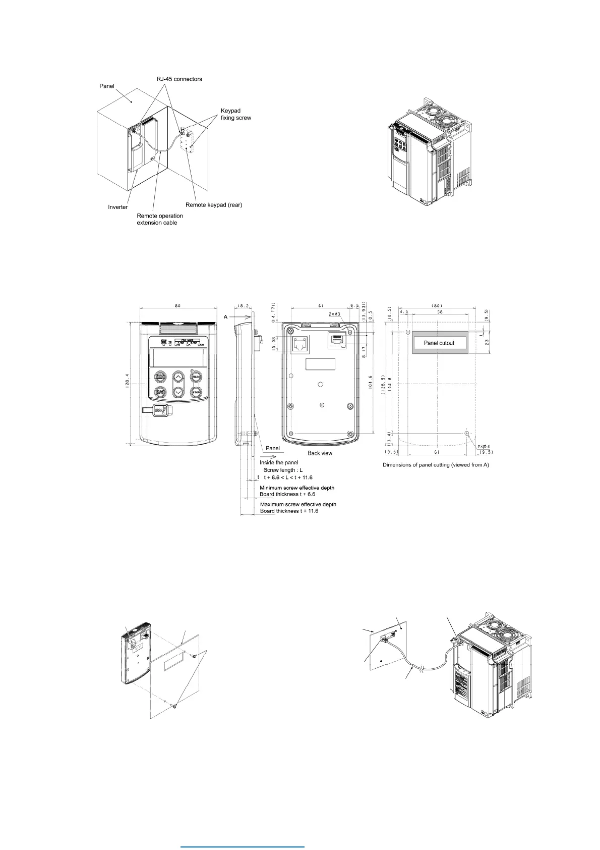
Figure 2.1 Mounting a Remote Keypad on the Panel Figure 2.2 Mounting a Remote Keypad on the inverter
(
In case of FRENIC-MEGA series)
Mounting the remote keypad on the panel (Figure 2.3)
Cut the panel out for a single square area and perforate two screw holes on the panel wall as shown in Figure 2.3.
Figure 2.3 External Dimensions, Dimensions of Square Cut-out and Screw Holes
Mount the remote keypad onto the panel
wall with 2 screws.
(Recommended tightening torque: 0.7 N·m)
Using a remote operation extension cable or commercially
available LAN cable, connect the remote keypad to the
inverter (insert one end of the cable into the RJ-45 connector
on the remote keypad and the other end into that on the
inverter).
Figure 2.4 Mounting the Remote Keypad
Figure 2.5 Connecting the Remote Keypad to the Inverter
with the Remote Operation Extension Cable or
LAN Cable(In case of FRENIC-MEGA,Lift series)
RJ-45 connector
Panel
M3
(To be provided
by the customer)
RJ-45 connector
(Remote keypad)
RJ-45 connector
(Inverter unit)
Panel
Remote operation extension cable
or LAN cable
Remote keypad
Dealers Industrial Equipment -- Visit https://DealersElectric.com or call (908) 688-1966 for all of your electric motor & VFD needs!
 Loading...