Ethernet-I/P Fieldbus Expansion Unit
PAGE 15
●
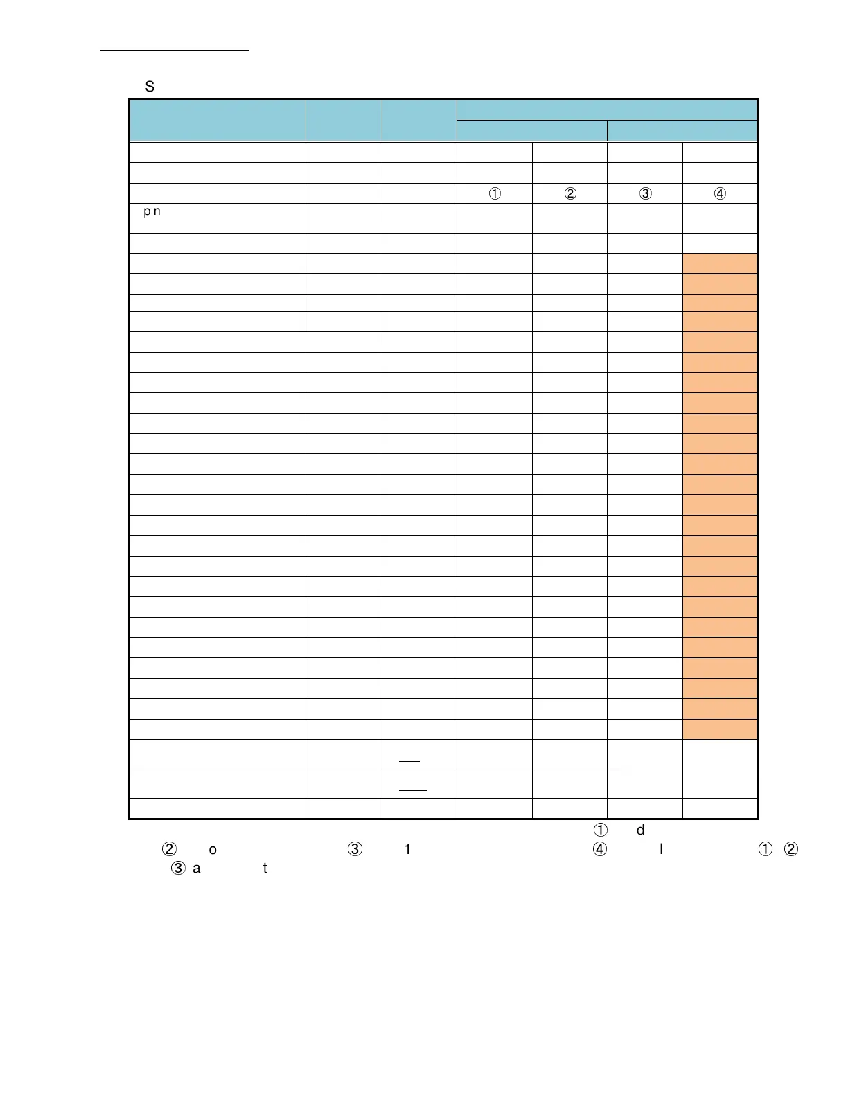
Spindle Format Output Items (BCD Format)
Output Items
Number of
Bytes
Fastening
Data
Spindle format
LSB (1word) MSB (2 word)
Spindle No. (1 to 32)
2 1
00 01
- -
PAR No. (1 to 32)
2 2
00 02
- -
Spindle Judgment*1
4
①
②
③
④
Spindle Cycle Count (8
digits)
4 123456 00 12 34 56
TOOL Cycle Count (8 digits)
4 12345678 12 34 56 78
Peak Torque*2
4 12.34 00 12 34 02
Final Torque*2
4 12.34 00 12 34 02
Snug Torque*2
4 5.67 00 05 67 02
1st Peak Torque*2
4 12.34 00 12 34 02
2nd Peak Torque*2
4 12.34 00 12 34 02
Final Angle*2
4 123.4 00 12 34 01
Differential Angle*2 4 -12.3 00 01 23 11
Rate 1*2 4 1.234 00 12 34 03
Rate 1 Increment Torque*2 4 12.34 00 12 34 02
Rate 1 Increment Angle*2 4 123.4 00 12 34 01
Rate 2*2
4
-0.123 00 01 23 13
Rate 2 Increment Torque*2
4
12.34 00 12 34 02
Rate 2 Increment Angle*2
4
123.4 00 12 34 01
Rate 3*2
4
0.123 00 01 23 03
Rate 3 Increment Torque*2
4
12.34 00 12 34 02
Rate 3 Increment Angle*2
4
123.4 00 12 34 01
1st Time*2
4 123.456 12 34 56 03
2nd Time*2
4 123.456 12 34 56 03
Cycle Time*2
4 654.321 65 43 21 03
Peak Current*2 4 12.3 00 01 23 01
Angle at Peak Torque*2
4 123.4 00 12 34 01
Rundown Revolutions*2
4 12.34 00 12 34 02
ZERO Voltage*2
4 -0.123 00 12 34 13
CAL Voltage*2
4 3.512 00 35 12 03
Spindle Cycle Count (4
digits)*3
2 123456 01 23 - -
TOOL Cycle Count (4
digits)*3
2
12345678 23 45 - -
Load rate 2
20 00 20
*1: In regards to the Spindle Judgment, “Judgment Data 1” is output as
①
, “Judgment Data 2” is output
as
②
, “Error Data” is output as
③
, and “1st Reject Item” is output as
④
. The values output as
①
,
②
,
and
③
are respectively set by bit allocation from “Fieldbus Message Setting” of the AFC3000 User
Console.
Note: shaded area described on next page
 Loading...
