Ethernet-I/P Fieldbus Expansion Unit
PAGE 21
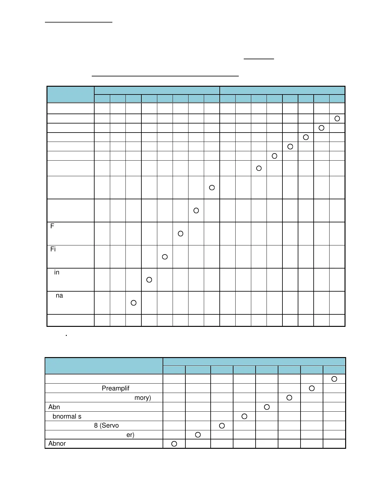
● Fastening Judgment Data Output Items: Example of Spindle Judgment Output Data 1 & 2 (common with
BCD and ASCII format)
The spindle fastening judgment (from a performed fastening cycle) is set by bit allocation of these 2
data bytes. These judgment status bits are set at the end of a completed fastening cycle.
Note: Actual Bit configuration is set using the AFC3000 software in the ‘Fieldbus Message Setup’
screen – Actual bit placement may differ than what is shown.
⋅ Judgment data setting (example from AFC3000 software)
Item
Logic
OR OR OR OR OR OR OR OR OR OR OR OR OR OR OR OR
ACCEPT
○
REJECT
○
ABNORMAL
○
BYPASS
○
STOP
○
RESET
○
Peak Torque
High Limit
○
Peak Torque
Low Limit
○
Final Torque
High Limit
○
Final Torque
Low Limit
○
Final Angle
High Limit
○
Final Angle
Low Limit
○
~
・
Error (Abnormal) Data Setting
The error data (Abnormal reason) of Spindle judgment is set by bit allocation of 1 byte. The data
corresponds to the abnormal state No. when an abnormal condition occurs.
Item
Abnormal state 1 (Torque Transducer)
○
Abnormal state 3 (Preamplifier)
○
Abnormal state 4 (System Memory)
○
Abnormal state 5 (Servo Amp Reply)
○
Abnormal state 6 (Servo Type)
○
Abnormal state 8 (Servo Amp)
○
Abnormal state 9 (Parameter)
○
Abnormal state 10 (Multi Signal)
○
 Loading...
