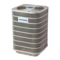
Do you have a question about the Fedders GWH18MC-D3DNA3A and is the answer not in the manual?
Instructions for safe installation and operation, including warnings, cautions, and symbol explanations.
Detailed technical specifications for the indoor and outdoor units, including capacity, power, and dimensions.
Graphs illustrating cooling and heating performance based on compressor speed and voltage.
Charts showing how cooling and heating capacity changes with outdoor temperature.
Data tables detailing operational parameters for cooling and heating modes.
Graphs illustrating noise levels for indoor and outdoor units based on operating conditions.
Detailed diagrams and dimensions of the indoor unit, including mounting requirements.
Diagrams and dimensions of the outdoor unit, showing installation clearances and components.
Schematic illustrating the refrigerant flow for both cooling and heating operations.
Wiring diagram for the indoor unit, showing connections between components and the control board.
Top and bottom views of the indoor unit's control PCB, showing component layout.
Top and bottom views of the outdoor unit's control PCB, showing component layout.
Details on various operating modes like Cooling, Heating, Fan, Auto, Sleep, and Timing functions.
Explanation of how indoor unit indicators display status, modes, and error codes.
Details on specific control functions like wind blow, buzzer, and auto button.
Covers sleep mode, general/moment timing, and dry/mildew proof settings.
Explains indoor fan speed settings, power-failure memory, and motor protection.
Details on Super Power mode, Health function, and thermo-bulb fault detection.
Covers thermo-bulb fault detection and forced running mode for indoor units.
Details on compensating and calibrating outdoor unit parameters and judging sensor effectiveness.
Explains cooling mode operations, temperature setting ranges, and conditions.
Details on operating conditions and temperature ranges for dehumidifying, air-supplying, and heating modes.
Explains defrosting control, compressor control logic, and outer fan control.
Covers 4-way valve operation in different modes and evaporator freeze prevention.
Details on overload protection mechanisms for cooling and dehumidifying modes.
Continues overload protection for cooling/dehumidifying and introduces heating overload protection.
Details on discharge temperature protection and frequency reduction for various conditions.
Details on power turn-off, overload protection continuity, and frequency reduction strategies.
Covers discharge temperature protection, power turn-off, frequency limiting, and overcurrent protection.
Details on voltage sag, communication faults, module protection, and overheating.
Covers module overheating, compressor overload, phase current, startup failure, out-of-step, and DC bus protection.
Details on DC bus voltage protection, abnormal four-way valve operation, and PFC protection.
Covers detection and handling of failures in various sensors like ambient, tube, and module temperature sensors.
Guidelines for selecting an installation location to avoid malfunctions caused by environmental factors.
Criteria for choosing a suitable location for the indoor unit, considering airflow and access.
Criteria for selecting an installation location for the outdoor unit, ensuring ventilation and noise management.
Covers essential electrical safety measures and proper earthing procedures for installation.
Steps for installing the rear panel, piping hole, drainage pipe, and wiring.
Procedure for routing and connecting power and signal wires between indoor and outdoor units.
Instructions for routing piping, wiring, and mounting the indoor unit.
Steps for connecting indoor and outdoor unit piping, including torque specifications.
Instructions for connecting electrical wiring to the outdoor unit.
Procedures for air purging, leakage testing, and condensate drainage for the outdoor unit.
Illustrated breakdown of the 230V 18K indoor unit components with part numbers.
Detailed list of parts for the 230V 18K indoor unit, including product codes and quantities.
Illustrated breakdown of the 230V 24K indoor unit components with part numbers.
Detailed list of parts for the 230V 24K indoor unit, including product codes and quantities.
Flowchart for diagnosing issues when the air conditioner does not start up.
Troubleshooting steps for issues related to refrigerant flow and air circulation.
Diagnosing problems with indoor fan, outdoor fan, or swing fan not running.
Troubleshooting compressor running problems, overheating, and lack of outdoor fan operation.
Diagnosing issues when the outdoor unit/compressor won't run, or when water leakage occurs.
Troubleshooting causes of abnormal sounds and shaking from the unit.
Overview of malfunction diagnosis, safety notes for capacitors, and discharge method.
Steps to confirm power supply and voltage before interpreting error codes.
Table and guide for interpreting error codes based on LED flashing patterns and AC status.
Detailed troubleshooting for error codes E5 (AC overload) through F9 (Air exhaust over high).
Troubleshooting for error codes U5 (current testing), P5 (overcurrent), H1-H3 (defrosting, overload, system abnormal), H4-H5 (IPM, PFC protection), HC, H7, H0, Lc, U1, EE, PU, P7-P8.
Troubleshooting for error codes U3 (DC bus voltage dips) through FH (Anti-freezing limit).
Diagnostic flowchart for capacitor charge faults in the outdoor unit control panel (AP1).
Diagnostic flowchart for IPM protection issues, including voltage checks and component testing.
Diagnosing high temperature and overload protection issues on the outdoor unit control board.
Flowchart for diagnosing compressor start-up failures, checking wiring and stopping time.
Diagnosing compressor out-of-step issues, checking system pressure, voltage, and fan operation.
Diagnosing overload and air exhaust malfunctions, checking PMV and refrigerant leakage.
Diagnosing PFC faults by checking the reactor and PFC capacitor, and performing resistance checks.
Diagnosing communication issues between indoor and outdoor units, checking wiring and boards.
Flowchart for detecting faults in the outdoor unit's communication circuit using voltage measurements.
Table of resistance values for ambient sensors at various temperatures for troubleshooting.
Table of resistance values for tube temperature sensors at various temperatures for troubleshooting.
Table of resistance values for air exhaust temperature sensors at various temperatures for troubleshooting.
Step-by-step instructions for disassembling the indoor unit, starting with the panel and filter.
Instructions for removing the front case, electric box cover, and electric box.
Steps for removing the evaporator and the fan motor from the indoor unit.
Steps for removing the outdoor unit's top cover, front panel, grille, and side plate.
Instructions for removing the electric box from the outdoor unit.
Steps for removing the axial flow fan blade and the motor assembly.
Procedure for desoldering and removing the four-way valve.
Steps for removing the gas/liquid valves and the compressor.
| Brand | Fedders |
|---|---|
| Model | GWH18MC-D3DNA3A |
| Category | Air Conditioner |
| Language | English |
