MicroPulse MPSxxU Manual
5
MPSxxU Light Head
Federal Signal www.fedsig.com
Installing and Maintaining the Light Head
Wiring the Light Head
REVERSE POLARITY/MISWIRING: To avoid damage to the light, ensure that the input voltage
is the same as the voltage rating of the light. Ensure that correct polarity is observed.The unit
must be properly fused with a 2 A fuse.
To wire the light head:
1. Determine the required functions and the length of wires needed to access them. A five-conductor
cable can be selected for a full-featured installation. For lengths up to 15 feet (5 m), use a minimum of
18AWG (1 mm
2
) wire. For lengths over 15 feet, use a minimum of 16 AWG (1.5 mm
2
) wire. Before wiring
the light head, refer to Table 3 for the function of each wire.
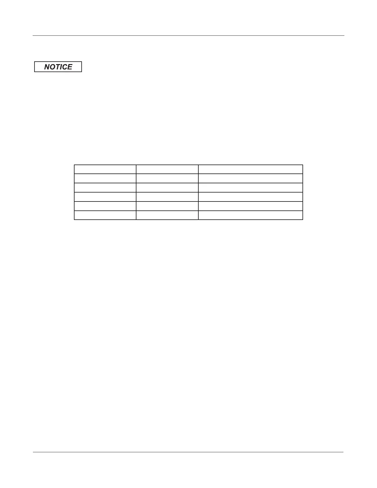
Table 3 Wire connections
Color Description Connection Point
Black Ground Battery Negative
Red Mode 1 Switched Positive 12-24 Vdc
White Mode 2 Switched Positive 12-24 Vdc
Brown Mode 3 Switched Positive 12-24 Vdc
Green Program/FSLink 12-24 Vdc (for Programming Only)
2. Strip 1/4 inch (5 mm) of insulation from the ends of the installer-supplied wires.
3. Use insulated butt connectors to connect the wires to the power cable of the light head. Ensure that
the connectors are securely crimped and properly insulated.
4. Connect the end of the fuse holder to the positive (+) terminal of the voltage source.
5. Connect the black wire from the light head to a known good vehicle ground as close to the light
head as practical.
6. The black wire is ground and must be connected to a suitable chassis ground if it cannot be taken
directly to the negative terminal of the battery.
7. The green wire has multiple functions: If using the light head with an external flasher, this wire is tied
directly to chassis ground. This allows an external flasher to control each color independently via the
Mode wires. If using the light head’s internal flasher, it is the runner wire that synchronizes FSLink
™
equipped products, and it serves as the function/pattern programming wire.
8. The red wire powers the light head in Mode 1 when connected to a fused, positive voltage.
9. The white wire powers the light head in Mode 2 when connected to a fused, positive voltage.
10. The brown wire powers the light head in Mode 3 when connected to a fused, positive voltage.
NOTE: Mode 3 overrides Mode 2, which overrides Mode 1.
 Loading...