14
Installation
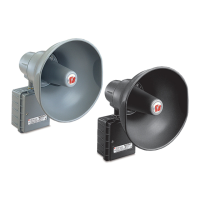
Modulator High-Powered Omni Speaker (MOD Series)
3. Hand tighten approximately a half turn after gasket engagement.
4. Locate the two (2) wires tie wrapped near the end of the horn throat. Note the label
on the back of the drivers and connect the solid wire to terminal 1 and the striped
wire to terminal 2 and white jumpers from 1 to 2 as shown in “Figure 6 Driver
Connections” on page 19.
Connecting driver wires out of phase may cause severe reduction in sound
output.
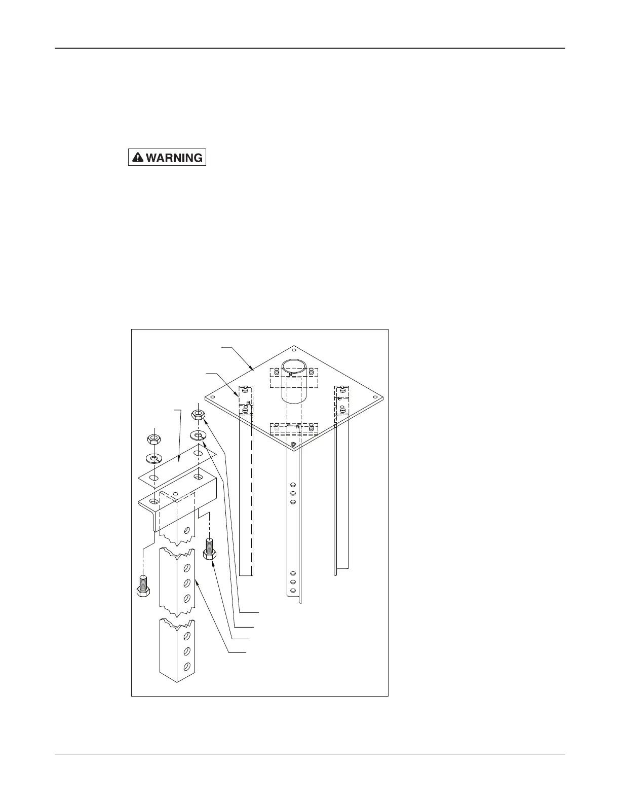
Wooden Pole Mounting
A typical wooden pole-mounted siren installation is shown in Figure 3. The siren
is mounted on a Class 2 utility pole (ANSI type wooden pole or equivalent) with a
minimum horizontal ground stress rating of 3,700 pounds (1678 kg). Ensure that soil
loads will conform to this size utility pole. It is attached to the pole by means of legs, as
shown in Figure 2.
Figure 2 Siren Leg Assembly
1/2-13 HEX NUTS (8)
SPLIT LOCKWASHERS (8)
1/2-13 HEX HD. BOLTS (8)
LEGS (4)
MODULATOR SIREN
BASE PLATE
LEGS (4)
SEE DETAIL
BELOW
291274A
RUBBER
INSULATOR
8570081
 Loading...