17
Installation
Description, Specications, Installation, and Service Manual
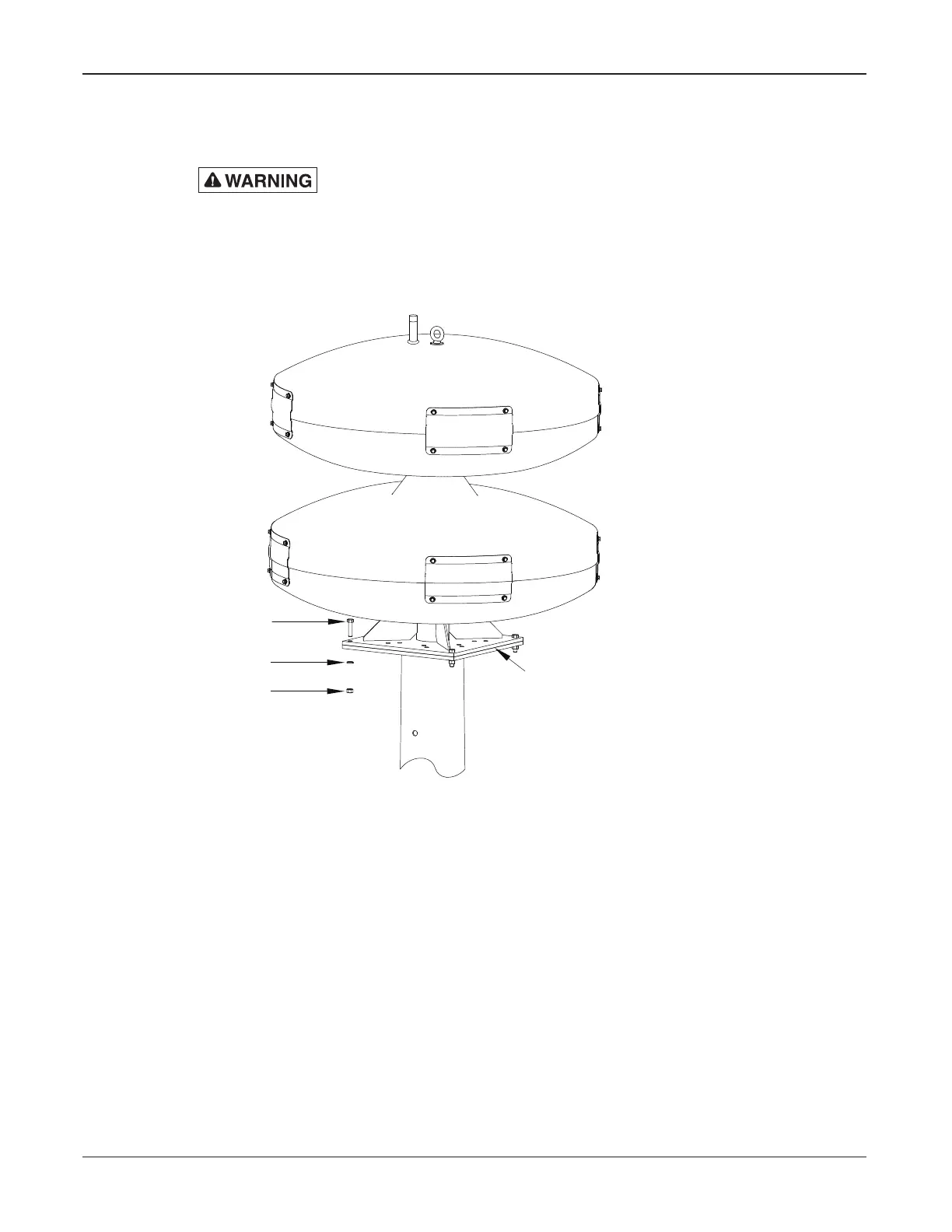
NOTE: Siren cable is run through the center of the mounting plate through the steel
pole. Siren cable can be pre-assembled through center of mounting plate for a no conduit
installation.
The eyebolt does NOT have sufcient strength to support the combined
weight of the siren and a utility pole. Therefore, do NOT attempt to erect the
pole and siren together using the eyebolt as a lifting point.
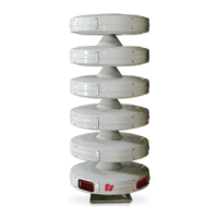
Figure 4 Steel Pole Mounting
1/2-13 X 2" LG.
S.S. SCREWS
1/2" SPLIT S.S.
LOCKWASHER
1/2-13 S.S. NUT
HEAVY
NOTE:
TO AVOID GALVANIC CORROSION
INSTALL RUBBER INSULATOR 8570080
BETWEEN SIREN BASE PLATE AND
POLE BASE PLATE.
USE S.S. SHIMS BETWEEN MTG. PLATES
IF MATING SUFACES ARE NOT FLUSH
TO AVOID WELDMENT CRACKS
3. Attach the modulator base to the pole’s top plate with rubber insulator 8570080
between them.
4. Use four of the stainless steel 1/2 in bolts, nuts, and lock washers provided.
(See Figure 4.) All mounting hardware needed is supplied in the hardware kit
shipped with this manual. Not all the hardware in the kit will be used in this type
of installation. Before tightening bolts, check mounting surfaces for warping. If
modulator base and top plate of pole have a gap greater than approximately 1/16 inch
between them, install galvanized or stainless steel shims to even out. Tighten bolts to
45-46 ft-lb torque.
 Loading...