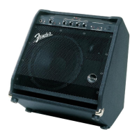
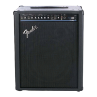
KXR 60
DELTACOMP™ (CONT)
As the capacitors charge, the negative voltage at the base of transistor Q8 turns on this Darlington device.
Current flows from the Collector of Q8 to pin 5 of U9. This current controls the output amplitude of U9.
The inverted output from U9 mixes with the signal at the input of U8B (pin 5) causing cancellation, which
reduces the input to the power amplifier. This prevents the amplifier from clipping. When the output of the
power amplifier is reduced, the Comparator toggles positive, removing the negative control voltage from
the attack/release circuit. The blocking action of Diodes CR14-CR17 force Capacitors C54-C57 to
discharge(Release) through a 4-pole filter with different time constants, through Resistor R85.
Turn-on delay
JFET Q7 and associated components provide a 2 - 3 second turn-on delay for the audio input to the power
amplifier. Upon power-up, the negative16 volts charges Capacitor C45 through Resistor R64. The
negative gate voltage pinches off the JFET, removing the ground from the input of the amplifier. When
switching the power off, C45 immediately discharges through Diode CR1, grounding the input of the
amplifier.
TROUBLE SHOOTING TIP: Check for proper operation of this circuit when experiencing excessive turn-
on or turn off “Pops”, or no output when signal applied to the input. Many times the JFET itself can be the
culprit. NOTE: Excessive turn-off “Pops” can also be caused by uneven discharge fo the +/- power
supplies. Usually a mismatch in the Filter Capacitors will cause this problem. It’s easy to look at both
supplies on an oscilloscope. Invert one scope input and check for even discharge to zero volts.
Power Amplifier
U10 is a high voltage op-amp (MC1436) that provides voltage gain for the power amplifier. Bootstrap
Capacitors C47 and C48 sense the output through R104. This provides more voltage swing for the opamp
with respect to the amplifier output.
Diodes CR2 - CR5 (BYV26D) make up the Fixed Bias circuit for the output transistors. The bodies of the
Diodes mount through the heatsink to properly track the temperature of the transistors. These Diodes were
selected because they exhibit a 2mV decrease in knee voltage for every 1 degree (Celsius) increase in
temperature. Pin 6 of U10 is at 0 Vdc. Therefore the Bias Diodes provide 2 voltage drops (1.2 volts) to the
base of Darlington output Transisitors Q5 and Q6.
Diodes CR6 - CR9 make up a voltage clamp protection circuit. If the bases of the output transistors reach
4.5 volts with respect to the output, the diodes will turn on, clamping the voltage.
The output signal feeds through the Headphone Jack before driving the 15” speaker and dual piezo horn.
Inserting a ¼” plug into the Headphone Jack will mute the speaker and horn.
PARTS LIST
PRINTED CIRCUIT BOARD ASSEMBLY
QTY PART # DESCRIPTION REFERENCE DESIGNATION
4 038690001 CAP AE AX 1.0uF 100V C18,25,43,46
5 026517001 CAP AE AX 2.2uF 100V C45,54,55,56,57
1 038692001 CAP AE AX 10uF 35V C51
19 009512001 CAP AE AX 22uF 25V 20% C1,2,5,7,8,11,13-15,20,23,24,33-36,49,50,64
4 049521000 CAP AE AX 47uF 50V C47,48,62,63
 Loading...


