13
The Maximum Forward Speed Bar can be adjusted in three
different positions to suit the desired maximum forward speed
of the operator. The positioning hole closest to the ground
speed control levers (labeled as #1 in Figure 6) is the lowest
setting and the positioning hole furthest from the ground
speed control levers (labeled as #3) is the fastest.
To adjust the position of the Maximum Forward Speed Bar
pull the T-handle knob (D) out to release the maximum
forward speed bar, position the Maximum Forward Speed Bar
in the desired location, and then release the T-handle knob.
Make sure that the T-handle knob locks the maximum forward
speed bar into place.
You should only adjust the position of the Maximum
Forward Speed Bar after you have stopped all movement
of the unit.
Ground Speed Control Levers:These levers control the
ground speed of the unit. The left lever (B, Figure6)controls
the left rear drive wheel and the right lever controls (C) the
right drive wheel.
FORWARD
NEUTRAL
REVERSE
Moving a lever forward increases the FORWARD speed of
the associated wheel, and pulling back on a lever increases
the REVERSE speed.
The ground speed control levers cannot be moved from the
NEUTRAL position until the parking brake lever is moved to
the DISENGAGED position.
Note:The further a lever is moved away from the neutral
position the faster the drive wheel will turn.
SeeDriving the Zero-Turn Riding Mowersection for steering
instructions.
Parking Brake:Pull the parking brake lever rearward
and up to engage the parking brake. Move the lever fully
forward and down to disengage the parking brake.
DISENGAGE:Releases the parking brake.
ENGAGE:Locks the parking brake.
Operator Platform: The operator stands on the operator
platform while driving the machine. Keep both feet on the
operator platform at all times.
The operator platform is integral to the safety interlock
system:
• If the operator steps off the operator platform while the
unit is running and the PTO switch is engaged, the PTO
will shut off.
Transmission Oil Fill: Transmission oil is added through the
hydraulic oil tanks. It also serves as extra holding capacity
for oil as the transmissions heat up and the hydraulic oil
expands. See Check / Fill Transmission Oil for oil level check
and fill procedures.
Fuel Tank Cap: To remove the cap, turn counter-clockwise.
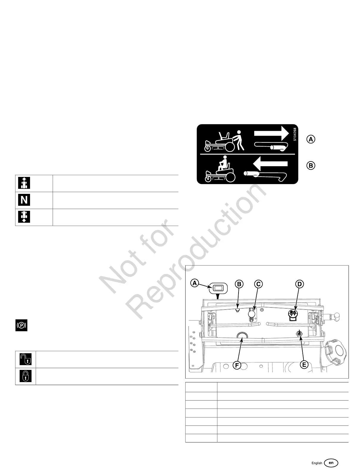
Transmission Release Levers:
A. Disengaged Position (Bypass Position)
B. Engaged Position (Run Position)
This unit is equipped with two transmission release levers.
The transmission release levers deactivate the transaxle
so that the unit can be pushed by hand. Both transmission
release levers must be in the same position whether you are
driving the unit or pushing it by hand. SeePushing the Unit by
Handfor operational information.
7
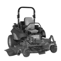
Callout Control Name
A Hour Meter
B Choke
C Throttle Control
D PTO (Power Take Off) Switch
E Ignition Switch
F Fuel Level Gauge