8
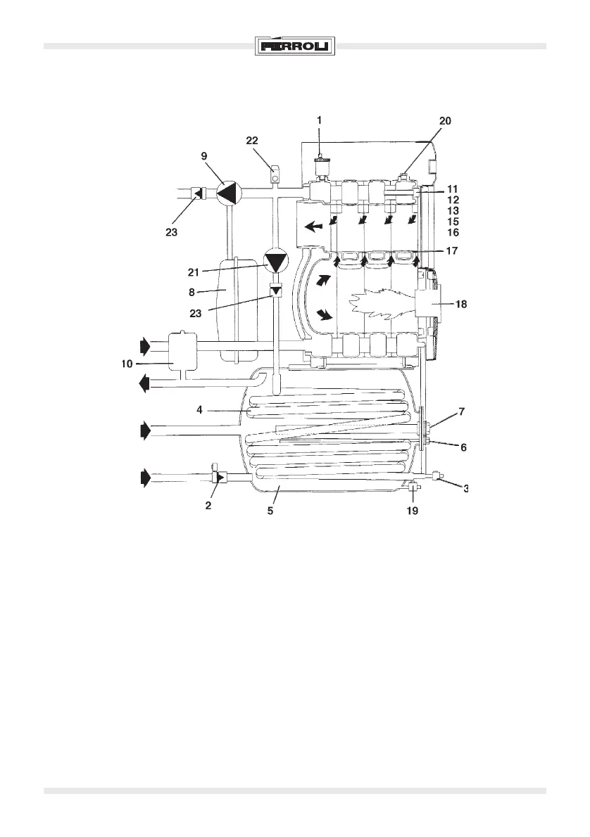
Fig. 4
KEY
1 Automatic air vent
2 Safety valve
3 Cock drain
4 Coil
5 Boiler
6 Safety thermostat boiler
7 Anode
8 Heating plant expansion tank (not supplied)
9 Circulating pump thermostat
10 Sanitary plant expansion tank (not supplied)
11 Boiler thermostat
12 Safety thermostat
13 Thermometer boiler
14 Thermometer boiler
15 Safety thermostat
16 Circulating pump thermostat
17 Boiler shell
18 Burner
19 Cock drain boiler
20 Water gauge
21 Circulating pump boiler
22 Safety valve (not supplied)
23 Non-return valve
2.03 Hydraulic diagram
Flow
Return
Hot sanitary
water outlet
Recirculation
Cold sanitary
water inlet
 Loading...