EasyManua.ls Logo

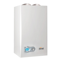
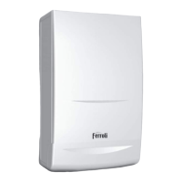
Ferroli F30 User Manual

Ferroli F30
48 pages
To Next Page IconTo Next Page
Page #1 background imageLoading...
Page #1 background image
Appr. nr. B99.06 A - CE 0461 BM 0607
FERROLI F30
Copper Wall-Mounted Combination,
Gas Fired Boiler for Central Heating
and Domestic Hot Water Production,
Fan Assisted, Room Sealed Compartment,
Electronic Flame Ignition and Control
3544016/0 - 07/2001
INSTALLATION, SERVICING AND
USER INSTRUCTIONS
G.C. NO: 47-267-24

Table of Contents

Other manuals for Ferroli F30

Question and Answer IconNeed help?

Do you have a question about the Ferroli F30 and is the answer not in the manual?

Ferroli F30 Specifications

General IconGeneral
Max. Heat Output (kW)30
ModulationYes
IgnitionElectronic
Safety featuresOverheat protection, Flame failure device, Frost protection
Fuel TypeNatural Gas

Summary

Technical and Dimensional Characteristics

Detailed Technical Data

Performance, Pressure, and Gas Data

Tables detailing heat output, input, pressures, gas flow rates, and water production.

Installation Details and Safety Requirements

Central Heating and DHW Installation Details

Flue Terminal Positions and Clearances

Two Pipe Flue System Installation Guide

Back Flue Connection Installation Procedure

Back Flue Outlet Installation Steps

Inner Flue and Boiler Securing

System Connections and Requirements

Electrical Safety and Air Pressure Switch

Commissioning and Testing Procedures

Pre-Startup Checks and Safety

Checks required before initial boiler startup, including gas, water, and electrical systems.

Boiler Startup and Operational Modes

Procedure for starting the boiler in central heating or domestic hot water modes.

Adjustment and Gas Conversion Procedures

Boiler Adjustments and Gas Conversion

Maintenance and Servicing Procedures

Annual Servicing Requirements and Checks

Checklist for annual servicing, including water pressure, safety devices, and burner cleanliness.

Detailed Boiler Servicing Procedure

Step-by-step guide for servicing the boiler, including electrical and gas checks.

Flue Gas Analysis Procedure

Component Replacement Procedures

Initial and Final Procedures for Part Replacement

General steps before and after replacing boiler components, including isolation and checks.

Replacing Control Panel and Gas Valve

Step-by-step instructions for removing and replacing the control panel and gas valve.

Component Replacement Procedures (Continued)

Replacing the Air Pressure Switch

Procedure for isolating and replacing the air pressure switch.

Removing the Burner and Injectors

Steps for removing the burner assembly and individual injectors for cleaning or replacement.

Replacing Electrodes and Flowmeter

Instructions for removing and replacing spark/flame electrodes and the DHW flowmeter.

Replacing the Pump and Heat Exchanger

Procedures for replacing the pump head/body and the boiler heat exchanger.

Replacing Sensors and Safety Valve

Instructions for replacing DHW/CH sensors, water pressure switch, and safety valve.

Removing the Fan and Thermostats

Procedures for removing the fan and limit or overheat cut-off thermostats.

Fault Finding and Operating Sequence

Boiler Operating Sequences (CH & DHW)

Describes the operational sequence for central heating and domestic hot water modes.

PCB Fault Finding and Indicator Lights

MF03 PCB Fault Diagnosis and Lights

Interprets LED indicators and diagnoses faults related to the MF03 PCB.

Troubleshooting Common Boiler Faults

Guides through diagnosing issues like no ignition, no DHW, or no heating.

Component Details and Spares List

General Test and Fault Finding

Fault Finding Chart 1: Electrical and Water Checks

Flowchart for diagnosing electrical supply, water pressure, and frost protection issues.

Fault Finding Charts

Fault Finding Chart 2: DHW Operation Checks

Flowchart for diagnosing issues specifically related to domestic hot water production.

Fault Finding Chart 3: Central Heating Operation Checks

Flowchart for diagnosing issues related to central heating operation.

Fault Finding Charts (Continued)

Fault Finding Chart 4: Fan and Flue Gas System Checks

Flowchart for diagnosing problems with the fan and flue gas system.

Fault Finding Chart 5: Modulation Checks

Flowchart for checking burner flame modulation in DHW and CH modes.

Fault Finding Chart 6: Ignition System Checks

Ignition System Diagnosis Steps

Flowchart to diagnose issues with the boiler's ignition system.

Electrical and Functional Schemes

Wiring Diagrams and Component Key

User Instructions and Controls

Boiler Operation, Safety, and Maintenance

Time Clock Programming and Operation

Related product manuals