FERROLI F30
11
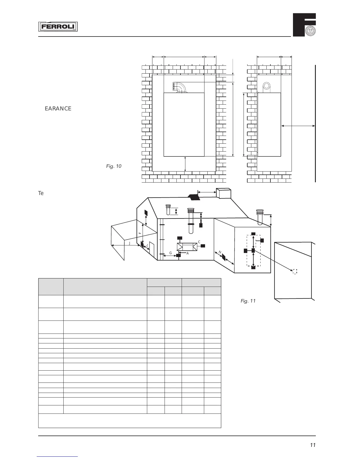
Terminal Position
F
ig.
11
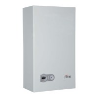
CLEARANCES:
* 600mm minimum clearance for servi-
cing access
460 5 min.5 min.
100 min.837
600* min.
760
200 min.
363 50 mm
Fig.
1
0
P
D, E
Q
Q
l
B
C
A
G
F
L
J
H
H
K
N
N
MM
Q
Directly below an opening, air brick, (0-7 kW)
opening windows, etc. (>7-14 kW)
(>14-32 kW)
(>32-70 kW)
Above an opening, air brick, (0-7 kW)
opening windows, etc. (>7-14 kW)
(>14-32 kW)
(>32-70 kW)
Horizontally to an opening, air brick, (0-7 kW)
opening windows, etc. (>7-14 kW)
(>14-32 kW)
(>32-70 kW)
Below gutters, soil pipes or drain pipes
Below eaves
Below balconies or car port roof
From a vertical drain pipe or soil pipe
From an internal or external corner
Above ground roof or balcony level
From a surface facing the terminal
(also see 6.1.2)
From a terminal facing the terminal
From an opening in the car port ( e.g. door,
window) into the dwelling
Vertically from a terminal on the same wall
Horizontally from a terminal on the same wall
From the wall on which the terminal is mounted
From a vertical structure on the roof
Above intersection with roof
Dimensions Terminal position
(kW input expressed in net)
Balanced flues room
sealed
Open flues
Natural
draught
Natural
draught
Fanned
draught
Fanned
draught
A
a
300 mm
600 mm
1500 mm
2000 mm
300 mm Not allowed 300 mm
B
a
300 mm
300 mm
300 mm
600 mm
300 mm Not allowed 300 mm
C
a
300 mm
400 mm
600 mm
600 mm
300 mm Not allowed 300 mm
D 300 mm 75 mm Not allowed 75 mm
E 300 mm 200 mm Not allowed 200 mm
F 600 mm 200 mm Not allowed 200 mm
G 300 mm 150 mm
b
Not allowed 150 mm
H 600 mm 300 mm Not allowed 200 mm
I 300 mm 300 mm Not allowed 300 mm
J 600 mm 600 mm N/A 600 mm
K 600 mm 1200 mm N/A 1200 mm
L 1200 mm 1200 mm N/A 1200 mm
M 1500 mm 1500 mm N/A 1500 mm
N 300 mm 300 mm N/A 300 mm
O N/A N/A N/A 50 mm
P N/A N/A See Table 2
and Fig. 6b
N/A
Q N/A N/A See Table 2
and Fig. 4
150 mm
NOTE N/A = Not applicable
a
In addition, the terminal should not be nearer than 150 mm (fanned draucht) or 300 mm (natural draught) to an opening in the building fabric formed for the purpose of accommodating
a built-in element such as a window frame, (see Figure C2). Separation distances are linked to the rated heat inputs as shown.
b
This dimension may be reduced to 75 mm for appliances of up to 5 kW heat input.
Minimum dimensions of fl ue terminal positions