FERROLI F30
2
4
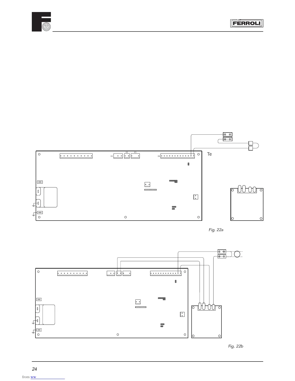
Terminals for integral clock
situated on circuit board
compartment
Existing wiring
3.13 Time clock fi xing
- Remove outer case by removing two securing screws from the rear bottom corners and lift off.
- Remove screw securing facia panel and swing facia panel down.
- Remove rear cover from facia.
- Remove clock blanking plate from the boiler facia panel.
- Mount clock into facia panel using two screws and spacers provided.
- Take the black cable containing the blue and brown wires and connect the loose spades to clock
terminals 1 & 2.
• Connect the plug end of the cable to terminal X2 contacts 1 + 2 of main circuit board.
- Remove the connector link from the 2 wires located behind the clock position.
- Connect these to terminal 3 and 5 of the clock.
- Replace everything in reverse order.
- Please refer to page 43 of User manual for use of time clock
F
ig.
22
a
X6
X1
X2 X3
X4
12121312345678910 12345678910111213
21
X5
X12
12
123456789
X10
X8
X7
MF03F
JP02
JP01
JP03
Nat/LPG
X11
CLOCK
12 35
4
3
X6
X1
X2 X3
X4
12121312345678910 12345678910111213
21
X5
X12
12
123456789
X10
X8
X7
MF03F
JP02
JP01
JP03
Nat/LPG
X11
CLOCK
3
72
12 35
VOLTAGE
FREE
SWITCH
Wiring for integral clock and/or external controls
External control i.e.
Room Stat or pro-
grammable room
thermostat
Terminal 3 & 4 situated under-
neath the boiler in the terminals
compartment
Fig.
22
b