FERROLI F30
10
Central Heating
Detailed recommendations are given in BS6798, BS5449, BS6700 and CP342 Part 2. Pipework not forming part
of the useful heating suface should be insulated to prevent any heat losses or possible freezing (i.e. in roof spaces
or ventilated underfl oor spaces). Drain taps should be positioned at the lowest point of the system in accessible
locations to permit the whole system to be drained down. The drain taps should be in accordance with BS2879. Copper
tubing to BS2871, Part 1 is recommended for water carrying pipework. Pipework in horizontal runs should have a
gradient where possible to facilitate the removal of air. Ensure that the boiler heat exchanger is not a natural point for
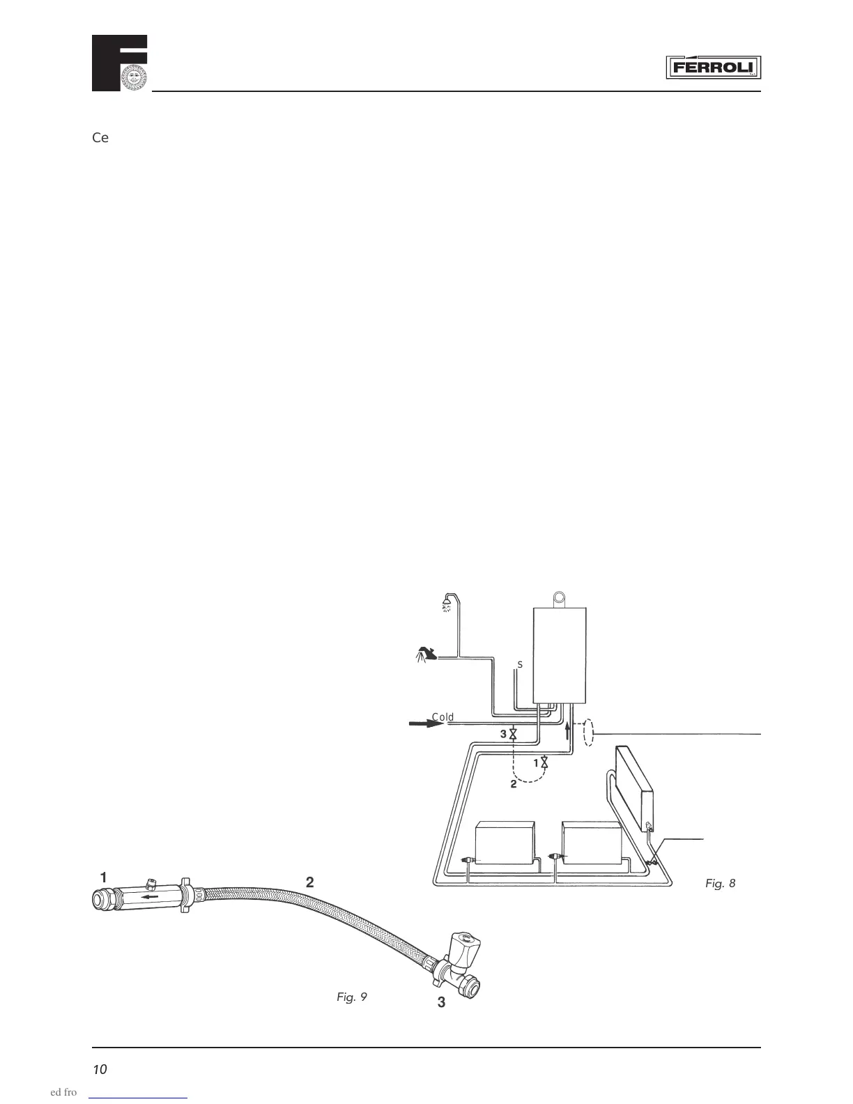
air collection. A typical heating system with domestic hot water circuit is illustrated in fi g. 8.
Important - If thermostatic radiator vales are fi tted a bypass must be fi tted to ensure a minimum fl ow rate through
the boiler of 6 l/min. The bypass should be fi tted as far as possible from the boiler.
Make Up Water
Provision must be made for replacing water lost from the sealed system. Reference should be made to BS6798,
for methods of fi lling and making up sealed systems. There must be no direct connection between the boiler's
central heating system and the mains water supply. The use of mains water to charge and pressurise the system
directly, is conditional upon the Local Water Byelaws. Again any such connection must be disconnected after use.
A typical temporary fi lling loop is shown in fi g. 9.
Domestic Hot Water
Always fi t a scale reducer in "hard water areas" (18 clarke degrees or over)". A 15mm copper connection point on the
boiler for attaching to the main supply is provided. The maximum domestic water pressure for the inlet supply is 10 bar
(145 P.S.I.). If the cold mains supply exceeds 5 bar (72 P.S.I.), a water governor or pressure reducing valve must be
fi tted by the installer into the mains supply in an inconspicuous but accessible position preferable between 3 and 5 metres
(10-16ft) before the appliance. Such a valve must be approved by the Water Research Council.
Attention - is drawn to the Model Water Byelaws.
Fittings manufactured from duplex (alpha-beta) brass are not acceptable for underground use and certain water
undertakings will not accept their use above ground.
Ensure all pipework is adequately supported
NOTE: A bypass must be fi tted as far as possible
from the boiler if thermostatic radiator valves are
fi tted thoughout.
F
ig. 8
Gas
Cold water
Additional expansion
vessel C.H. (if required)
Filling
point C.H.
Bypass
Key
1. Filling point C.H.
2. Temporary connection
3. Cold water supply
Fig.
9