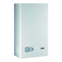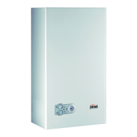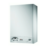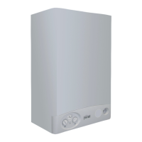
Do you have a question about the Ferroli Ferella F 24-30 MEL and is the answer not in the manual?
General introduction to the high-efficiency heat generator for central heating and hot-water.
Important safety instructions for installation, maintenance, and operation to prevent injury or damage.
Details conformity to applicable European directives and CE marking.
Provides dimensional drawings and connection points for the Domina F 24 E version.
Illustrates the F 24 E/MEL version, identifying key internal and external components.
Presents detailed technical specifications for 24kW and 30kW versions, including powers, gas, and electrical data.
Details the hydraulic circuit for heating, including components and flow path.
Explains the function and operation of the circulator in the heating system.
Describes the purpose and location of the air separator in the heating circuit.
Details the expansion tank's role in compensating for thermal expansion of water.
Explains the construction and function of the copper laminar twin heat exchanger.
Details the hydraulic unit and its integrated components like safety valve and pressure switch.
Explains the hydraulic circuit for tap water production and flow control.
Details the flow meter for tap water and the flow-rate restrictor's function.
Illustrates the gas circuit, showing gas inlet, valve, and connections.
Explains the operation of the gas valve, including its two operators for control and modulation.
Step-by-step guide for adjusting minimum and maximum burner gas pressure.
Procedure for converting the unit between natural gas and LPG operation.
Explains the burner unit, including manifold, nozzles, ignition, detection electrodes, and assembly.
Covers fume deflector, airtight chamber, and fan/pressure switch functions for exhaust.
Details the operation and checks for the air pressure switch in the fume circuit.
Guidance on fume duct installation, including diaphragm selection and replacement.
Example calculation for separate fume outlet, including condensate trap recommendation.
Details electrical connections, terminal board layout, and wiring diagrams.
Explains the function and role of the main electronic control card.
Describes the operation and function of safety and limit thermostats.
Explains the NTC sensors for heating and tap water temperature.
Explains how the boiler functions for heating and hot water production.
Covers test function, post-circulation, anti-locking, antifreeze, and gradual start.
Visual representation of boiler operation modes in summer and winter.
Description of control panel LEDs, buttons, and settings.
Guide to adjusting room, system, and hot water temperatures, and summer/winter mode.
Details potentiometer settings (P1-P5) and jumper configurations for operation.
Troubleshooting guide for electrical supply, system pressure, and antifreeze protection.
Diagnostic flow chart for hot water operational problems.
Diagnostic flow chart for heating operational problems.
Troubleshooting guide for fan, fume circuit, and pressure switch problems.
Diagnostic flow chart for ignition failures and burner start-up issues.
Troubleshooting guide for burner modulation in heating and hot water modes.


