EasyManua.ls Logo

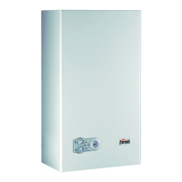
Ferroli Domina Oasi F 30 E User Manual

Ferroli Domina Oasi F 30 E
40 pages
To Next Page IconTo Next Page
Page #1 background imageLoading...
Page #1 background image
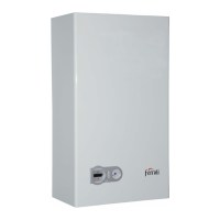
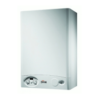
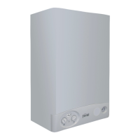
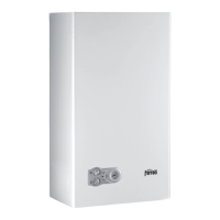
DOMINA OASI F 24-30 E
FERELLA BOIL F 24-30 MEL
KEA AIR COMPACT E
Wall-Mounting
Gas Boiler
Airtight Chamber,
for Heating and Hot
Water with
Integrated Boiler
TECHNICAL
MANUAL
EDITION
09•2002
Question and Answer IconNeed help?

Do you have a question about the Ferroli Domina Oasi F 30 E and is the answer not in the manual?

Ferroli Domina Oasi F 30 E Specifications

General IconGeneral
BrandFerroli
ModelDomina Oasi F 30 E
CategoryBoiler
LanguageEnglish

Summary

General Technical Characteristics and Data

General Warnings

Crucial safety instructions for installation, maintenance, and proper usage of the boiler.

1.4 Technical data table

Table of specifications, performance data, and connection sizes for different boiler models.

Product Framework and Internal Components

2.1 Hydraulic circuit - heating

Diagram and explanation of the boiler's hydraulic circuit for heating purposes.

2.2 Hydraulic circuit – tap water

Diagram and explanation of the hydraulic circuit responsible for tap water heating.

Adjusting burner pressure

Procedure for setting minimum and maximum burner pressure for optimal combustion.

2.6 Electrical circuit

Overview of the boiler's electrical circuit, terminal board, and wiring diagram.

Operation

3.5 Operating parameter adjustment

Details on adjusting boiler parameters P1-P5 and jumper configurations for gas type and pump system.

Troubleshooting

Flow Diagram 1: Checking Electric Power Supply - System Pressure and Antifreeze Protection

Flowchart for diagnosing issues related to power supply, water pressure, and antifreeze protection.

Flow Diagram 2: Checking Hot Water Operation

Flowchart for diagnosing problems with the hot water production function of the boiler.

Flow Diagram 3: Checking Heating Operation

Flowchart for diagnosing problems with the heating system operation of the boiler.

Flow Diagram 4: Checking Fan/Fume Circuit

Flowchart for diagnosing issues related to the fan and fume evacuation system.

Flow Diagram 5: Checking Ignition

Flowchart for diagnosing and resolving issues with the burner ignition sequence.

Flow Diagram 6: Check the Modulation of the Hot Water and Heating

Flowchart for checking flame modulation in both hot water and heating operational modes.

Related product manuals