Do you have a question about the Ferroli Domina F 24-30 E and is the answer not in the manual?
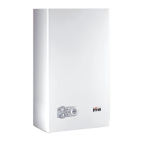
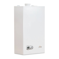
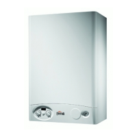
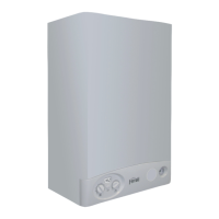
Appliance is a high-efficiency heat generator for central heating and hot-water.
Details the physical dimensions and connection points of the boilers.
Identifies key components of the boiler through diagrams and a key.
Provides detailed technical specifications for the boilers in a tabular format.
Illustrates the hydraulic flow for the heating system with component labels.
Shows the hydraulic flow for tap water operation with component labels.
Displays the gas supply and distribution system within the boiler.
Details the components and operation of the burner unit, including electrodes.
Explains the exhaust system, including the fan and fume ducts.
Outlines the wiring diagram and terminal board layout for the boiler's electrical system.
Explains how the boiler functions for heating and hot water under various conditions.
Provides flowcharts for summer and winter operating modes and fault indications.
Describes the LEDs, knobs, and gauges on the boiler's control panel.
Details how to adjust room temperature, system temperature, and hot water settings.
Explains adjustments for temperature, capacity, and gas pressure using potentiometers and jumpers.
A flowchart for diagnosing power, pressure, and antifreeze issues.
A flowchart for troubleshooting problems with hot water supply.
A flowchart for diagnosing issues related to the heating function.
A flowchart for troubleshooting fan and fume evacuation problems.
A flowchart to diagnose ignition failures and burner startup issues.
A flowchart to check the boiler's modulation capability for heating and hot water.
| Efficiency | 93% |
|---|---|
| Max working pressure | 3 bar |
| Type | Gas Boiler |
| Fuel Type | Natural Gas or LPG |
| Ignition | Electronic |


