EasyManua.ls Logo

Ferroli RVL 38/3 Series User Manual

Ferroli RVL 38/3 Series
42 pages
To Next Page IconTo Next Page
Page #1 background imageLoading...
Page #1 background image
RVL
REFRIGERATORI E POMPE DI CALORE D’ACQUA
RAFFREDDATI AD ARIA CON VENTILATORI ELICOIDALI
AIR COOLED WATER HEAT PUMPS AND
CHILLERS WITH HELICAL FANS
MANUALE INSTALLAZIONE ED USO
INSTALLATION AND OPERATION MANUAL
GB
I

Table of Contents

Question and Answer IconNeed help?

Do you have a question about the Ferroli RVL 38/3 Series and is the answer not in the manual?

Ferroli RVL 38/3 Series Specifications

General IconGeneral
BrandFerroli
ModelRVL 38/3 Series
CategoryHeat Pump
LanguageEnglish

Summary

General Specifications

Hydraulic and Chilling Circuit Components

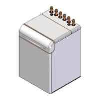
Explains the various components involved in the unit's hydraulic and refrigerant circuits.

Electric Circuit Components

Details the main electrical components and their functions within the unit's control system.

General Specifications - IR Unit for Cooling Mode Only

General Specifications - IP Heat Pump Unit

Unit Technical Specifications

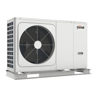
Provides general technical data for the IP heat pump unit.

Electrical Connections

Electric Panel Structure and Components

Describes the layout and main components within the unit's electrical panel.

Single-Phase Unit Wiring Diagrams

Illustrates electrical connections for single-phase models.

Three-Phase Unit Wiring Diagrams

Illustrates electrical connections for three-phase models.

Wet Connections

Hydraulic Circuit Diagram and Connection Layout

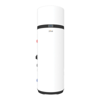
Illustrates the water supply circuit connections for the unit.

Winter Standstill Ice Prevention

Outlines solutions to prevent freezing damage during winter shutdowns.

Quick Wet Coupling Installation Guide

Step-by-step instructions for installing quick wet couplings (AV).

Flexible Wet Coupling Installation Guide

Step-by-step instructions for installing flexible wet couplings (KT).

Water Pressure Drops

Operating Limits and Pressure Drop Graph

Illustrates water pressure drop based on flow rate and operating limits.

Useful Head

Head for Units 16-19-24-30 with Storage Module

Graph showing useful head for specific models with standard/high head modules.

Head for Units 38-42-50 with Storage Module

Graph showing useful head for specific models with standard head modules.

Operating Range

General Operating Limits

Defines the operating ranges for correct unit performance and warranty.

Monitoring System

Alarm Management and Reset

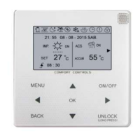
Explains how to identify, reset, and understand unit alarms and codes.

Menu Structure and Navigation

Details the hierarchical menu system for unit parameter configuration.

Setting at Work

Comprehensive Maintenance Procedures

Details routine inspections and specific maintenance tasks for the unit.

Safety and Pollution

Handling and Emergency Procedures

Covers safe handling of refrigerants, leak precautions, and first aid measures.

Related product manuals