EasyManua.ls Logo

Festo CMSX C-U-F1 Series User Manual

Festo CMSX C-U-F1 Series
8 pages
To Next Page IconTo Next Page
Page #1 background imageLoading...
Page #1 background image
Positioner
CMSX-...-C-U-F1-...
Festo AG & Co. KG
Postfach
73726 Esslingen
Germany
+49 711 347-0
www.festo.com
(en) Operating instructions 8059561
1602a
[8059563]
Original: de
Positioner CMSX English..............................................
For detailed specifications on the product, a complete description and the
declaration of conformity è www.festo.com/sp
1 Layout
1.1 CMSX-S-... (rotary)
45 6
7
8
6
666
123
9aJaA
aB
3
1 Housing cover
2 Inspection window for LCD display
3 Housing screws
4 Blanking plug
5 Cable entry with cable connector
6 Mounting thread
7 Shaft
8 Mechanical coupling
9 Back plate
aJ Housing
aA Pneumatic connections (G1/8)
aB Earth terminal
Fig. 1
1.2 CMSX-SE-... (linear)
123 45 6
7
89
6
666
3
aJ
1 Housing cover
2 Inspection window for LCD display
3 Housing screws
4 Cable entry with cable connector
for external displacement encoder
5 Cable entry with cable connector
for electrical connecting cable
6 Mounting thread
7 Base plate
8 Housing
9 Pneumatic ports (G1/8)
aJ Earth terminal
Fig. 2
12
4567
8
3
1 LCD display
2 Terminal strip 1 (pin 1 … 14)
3 Terminal strip 2 (pin 1 … 3)
4 Terminal strip 3 (pin 15, 16)
5 Set key
6 Sub key
7 Add key
8 Earth terminal
Fig. 3
Pin Designation Description
Terminal strip 1 (pin 1 … 14)
1 Usp+ Voltage input signal + Input setpoint value 0 … 10 V
2 Usp- Voltage input signal -
3 Isp+ Current input signal + Input setpoint value
4 … 20 mA, 0 … 20 mA
4 Isp- Current input signal -
5 +24 V DC Operating voltage supply; 24 V DC Supply to electronics and
valves
6 0 V DC Operating voltage supply; 0 V DC
7 I- Current output signal - Output actual value 4 … 20 mA
8 I+ Current output signal +
9 Connected at plant to earth terminal Do not modify the cable
10 ALARM Alarm digital output Alarm output
11 D-OUT1 Digital output Out 1 Status output
12 D-OUT2 Digital output Out 2
13 +24 V DC Load voltage supply for outputs;
24 V DC
Supply to digital outputs
14 0 V DC Load voltage supply for outputs; 0 V DC Supply to digital outputs
Terminal strip 2 (pin 1 … 3)
1 0 V DC Operating voltage - External displacement
encoder
2 U+ Sensor signal actual value (0 … 5 V DC)
3 +5 V DC Operating voltage +
Terminal strip 3 (pin 15, 16)
15 D-IN+ Digital input + Control input
1)
16 D-IN- Digital input - Control input
1)
1) Permits split circuits if separate power supply units are used
Fig. 4

Other manuals for Festo CMSX C-U-F1 Series

Question and Answer IconNeed help?

Do you have a question about the Festo CMSX C-U-F1 Series and is the answer not in the manual?

Festo CMSX C-U-F1 Series Specifications

General IconGeneral
Protection classIP65
Media temperature-20 ... 80 °C
Housing materialAluminum
Connection sizeG1/4
Ambient temperature-20 ... 80 °C

Summary

Layout

CMSX-S-... (rotary) Layout

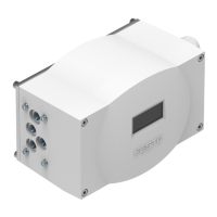
Details the layout and components of the CMSX-S rotary positioner.

CMSX-SE-... (linear) Layout

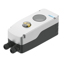
Details the layout and components of the CMSX-SE linear positioner.

Safety and Handling

Intended Use

Specifies the intended application and suitable actuators for the positioner.

Returning to Festo

Procedure for returning the product to Festo, including handling hazardous substances.

Function

Explains the operational principle of the positioner calculating signals for actuators.

Transport and Storage

Guidelines for safe transport and storage in a suitable environment.

Installation

Mechanical Installation

Instructions for mechanical mounting, including protection and adapter use.

Pneumatic and Electric Connections

Pneumatic Connections

Details on connecting compressed air supply and to the pneumatic actuator.

Electric Connections

Instructions for wiring electrical connections and ensuring IP65 protection.

Commissioning Procedures

Prerequisites for Commissioning

Checks and familiarization required before starting the commissioning process.

Check Operating Conditions

Ensuring stable voltage supply and checking connection tightness.

Switching On the Positioner

Step-by-step guide for powering on the positioner, setpoint, and compressed air.

Switch-On Behavior

Describes the positioner's status and display during initial start-up.

Initialisation Process

Guidance on performing manual or automatic initialisation for the positioner.

Menu Structure and Configuration

Menu Structure Diagram (Fig. 14)

Visual representation of the positioner's menu hierarchy and navigation.

Menu Structure Details

Menu Structure Diagram (Fig. 15)

Detailed breakdown of menu options for Parameter, Curve, Information, and Initialization.

Configuration Options and Technical Data

Menu Configuration Details

Detailed descriptions of menu settings for Signal, Open, Direct, Character, D-OUT, and D-IN.

Technical Data

Specifications including sensing range, operating pressure, temperature, and protection class.

Operation and Permitted Values

Guidelines for operating the positioner and adhering to permitted limit values.

Disassembly Procedure

Step-by-step instructions for safely disassembling the positioner.

Disposal Guidelines

Instructions for environmentally friendly disposal of the product.

Troubleshooting

Information and guidance for identifying and resolving operational faults.

Related product manuals