SFE1−LF−...
Festo SF E1−LF−... 0503NH Deutsch
10
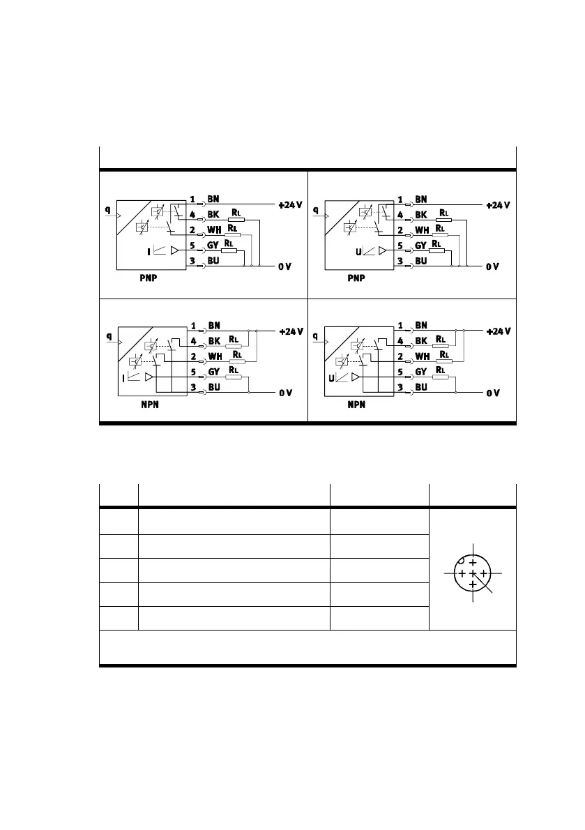
Schaltbilder SFE1−LF−...
SFE1−LF−...−...−P2I SFE1−LF−...−...−P2U
SFE1−LF−...−...−N2I SFE1−LF−...−...−N2U
Bild7
Verkabeln Sie den SFE1−LF−... wie folgt:
Pin
Belegung Kabelfarben
1)
Stecker
1 DC + 24 V Versorgungsspannung Braun (BN) 5−polig M12
2 Digitalausgang B (Out B) Weiß (WH)
1
3 0 V Blau (BU)
24
4 Digitalausgang A (Out A) Schwarz (BK)
5
5 Analogausgang C (Out C)
2)
Grau (GY)
3
1) Bei Verwendung der Anschlussdose mit Kabel lt. Zubehör
2) Spannung (U) oder Strom (I) siehe Technische Daten
Bild8
Anzugsdrehmoment max. 0,5 Nm.
 Loading...