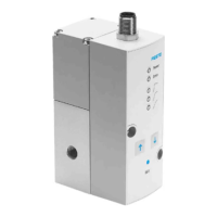
Proportional-Druckregelventil
VPP M-...C1 (LCD)
Festo AG & Co. KG
Postfach
D-73726 Esslingen
+49 711 347 0
www.festo.com
Bedienungsanleitung 754538
1204d
Original: de
Proportional-Druckregelventil VPPM-...C1 (LCD) deutsch...................
Hinweis
Einbau und Inbetriebnahme darf nur durch Fachpersonal mit entsprechender
Qualifikation gemäß dieser Bedienungsanleitung durchgeführt werden.
1 Produktbeschreibung
1.1 Anschlüsse, Befestigungsbohrungen und Bedienteile ( Muffenventil)
1
4
5
4
2
3
6
1 elektrischer Anschlussst ecker M12
(8-polig)
2 Anschluss Arbeitsluft (2),
Druckausgang
3 Anschluss Entlüftung (3 )
4 Durchgangsbohrungen zur Befesti-
gung
5 Anschluss Druckluft (1), Druckein-
gang
6 Typenschild
Fig. 1
1.2 Pneumatische Anschlüsse (Flanschventil)
1
2
3
1 Kanal (2) Arbeitsluft, Druckaus-
gang
2 Kanal (1) Dr uckluft, Druckeingang
3 Kanal (3) Entlüftung
Fig. 2
1.3 Anzeige-, Bedienelemente und Displaysymbole
1
2
3
4
1 Display
2 Taste DOWN
3 Taste EDIT
4 Taste UP
Fig. 3
2 Anwendung und Funktion
Das VPPM-...C1 dient bestimmungsgemäß zum Regeln eines Druckes proportional
zu einem vorgegebenen Sollwert. Ein integrierter Drucksensor nimmt dazu den
Druck am Arbeitsanschluss auf und vergleicht diesen Wert mit dem S ollwert. Bei
Soll-Ist-Abweichungen wird das Regelventil solange betätigt, bis der Ausgangs-
druck den Sollwert erreicht hat.
+W
-W
3
1
2
X
Druckeingang
Sollwert
Sollwert
Druckausgang
Entlüftung
Pin 6
Fig. 4
3 Varianten des VPPM-...
Typenschlüssel des VPPM-...
VPPM
-
6L
-
L
-
1
-
G18
-
0L6H
--
V1N S1C1
1
4
56
2
37
Pos. Merkmale Bedeutung
1 Nennweite in [mm]
Ventilart
6, 8, 12
F (Flansch), L (Muffe)
2 Dynamikklasse L(Low)
3 Ventilfunktion 1 (3-Wege-Druckregelventil,
Ruhestellung geschlossen)
4 Pneu. Anschluss
– Flansch/Anschlussplatte
–ISO-Gewinde
– NPT-Gewinde
F
G18 (1/8”), G14 (1/4”), G12 /1/2“)
N18 (NPT 1/8), N14 (NPT 1/4),
N12 (NPT 1/2)
5 Standard-Regelbereiche:
– unterer Druckwert
– oberer Druckwert
Alternative Regelbereiche:
1)
– unterer Druckwert
– oberer Druckwert
0L (0 bar)
2H (2 bar), 6H (6 bar), 10H (10 bar)
...L (... = Wert zwischen 0,1...10 bar)
z.B. 4L
...H (... = Wert zwischen 0,1...10
bar) z.B. 9H
6 – Sollwertvorgabe
–Schaltausgang
A4 (4 ... 20 mA), V1 (0 ... 10 V)
P (PNP), N (NPN)
7 Genauigkeit
Bediengerät
... (2 %, Standard), S1 (1 %)
... (LED), C1 (LCD)
1) Bei Verwendung eines alternativen unteren und oberen Druckwertes, kann die Gesamtgenauigkeit des
VPPM-…C1 nicht gewährleistet werden.
Fig. 5
4 Voraussetzungen für den Produkteinsatz
Warnung
Abhängig von der Funktionalität der Maschine/Anlage kann die Manipulation von
Signalzuständen schwere Personen- oder Sachschäden verursachen.
• Berücksichtigen Sie, dass das Ändern des Sc haltverhaltens der Schaltaus-
gänge im EDIT-Modus sofort wirksam wird.
• Aktivieren Sie den Passwortschutz (Sicherheitscode), um das versehentliche
Ändern durch unbefugte Dritte zu verhindern ( Abschnitt 6 unter EDIT-Mo-
dus).