Poportional pressure regulator
VPPM−...C1 (LCD)
Festo AG & Co. KG
Postfach
D−73726 Esslingen
++49/711/347−0
www.festo.com
Operating instructions 753 264
1007c
Original: de
Note
Installation and commissioning may only be performed in accordance with these
operating instructions by technicians with appropriate qualifications.
Note
The product is suitable for use only for industrial purposes.
In residential areas, measures for radio interference suppression may be necess
ary.
1 Product description
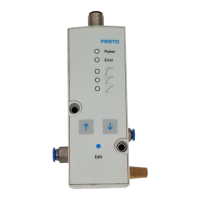
1.1 Connections, mounting holes and control sections (in−line valve)
1
4
5
4
2
3
6
1 Electrical connecting plug M12
(8−pin)
2 Air connection (2), pressure output
3 Exhaust connection (3)
4 Through−holes for fastening
5 Compressed air connection (1),
supply port
6 Rating plate
Fig.1
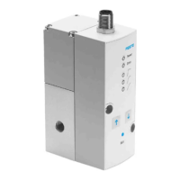
1.2 Pneumatic connections (flanged valve)
1
2
3
1 Duct (2) air, pressure output
2 Duct (1) compressed air , supply port
3 Duct (3) exhaust
Fig.2
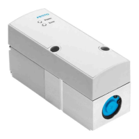
1.3 Display and control elements, display symbols
1
2
3
4
1 Display
2 DOWN button
3 EDIT button
4 UP button
Fig.3
2 Application and function
The VPPM−...C1 has been designed for regulating a pressure proportional to a
specified setpoint value. A built−in pressure sensor records the pressure at the
working line and compares this value with the setpoint value. If the actual value
differs from the setpoint value, the regulating valve is actuated further until the
output pressure reaches the setpoint value.
+W
−W
3
1
2
X
Supply port
Setpoint value
Setpoint value
Pressure output
Exhaust
Pin 6
Fig.4
3 Variants of the VPPM−...
Type code of the VPPM−...
1
23
5
6
4
7
VPPM
−
6L
−
L
−
1
−
G18
−
0L6H
−−
V1N S1C1
Item Properties Meaning
1 Nominal size [mm]
Valve type
6, 8
F (flanged), L (in−line)
2 Dynamic response class L (Low)
3 Valve function 1 (3−way pressure regulator
normally closed)
4 Pneumatic port
Flange/sub−base
ISO thread
NPT thread
F
G18 (1/8"), G14 (1/4")
N18 (NPT 1/8), N14 (NPT 1/4)
5 Standard control range:
Lower pressure value
Upper pressure value
Alternative control ranges:
1)
Lower pressure value
Upper pressure value
0L (0 bar)
2H (2 bar), 6H (6 bar), 10H (10 bar)
...L(... = value between 0.1...10 bar)
e.g. 4L
...H (... = value between
0.1...10 bar) e.g. 9H
6 Setpoint specification
Switching output
A4 (4 ... 20 mA), V1 (0 ... 10 V)
P (PNP), N (NPN)
7 Accuracy
Operator unit
... (2 %, standard), S1 (1 %)
... (LED), C1 (LCD)
1) When an upper and lower pressure value are used, it is not possible to guarantee the overall
accuracy of the VPPM−...C1.
Fig.5