Note
If the Y−connecting cable type NEBV−M12G8−KD−..−M12G5 is connected to CPX
I/O modules, the I/O modules will no longer be galvanically isolated.
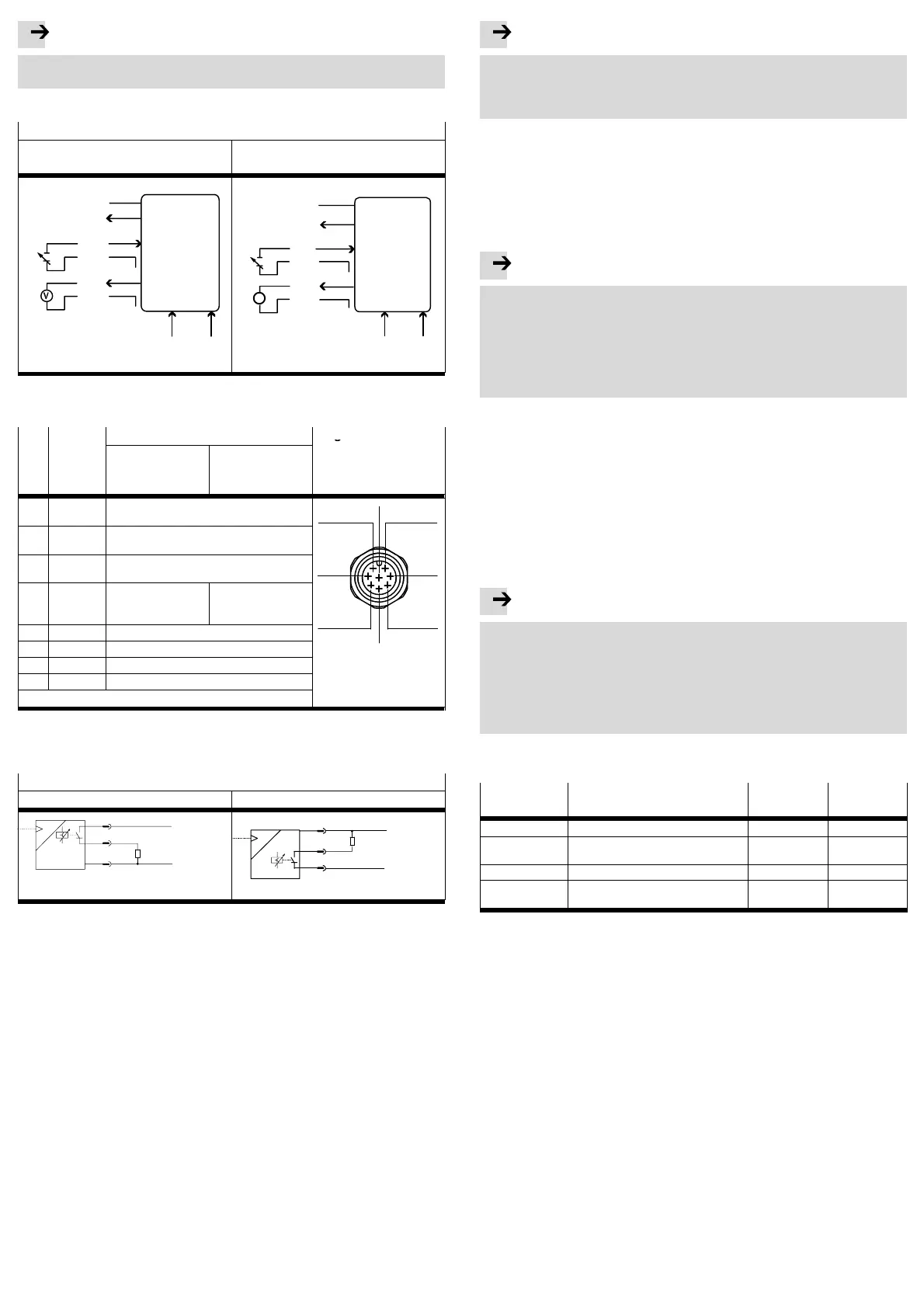
· Connect the cables of the VPPM−...C1 in accordance with the circuit diagram.
Circuit diagrams for the VPPM−...C1
Voltage variants
(type VPPM−...−V1...C1)
Current variant
(type VPPM−...−A4...C1)
W−
8
4
3
D1
ext in
D2
ext in
1
5
7
X
GND
6
W+
D3
out
U
v
0 ...10
V
2
PI N
A
7
8
4
3
D1
ext in
D2
ext in
1
5
X
GND
6
w−
D3
out
U
v
4 ...20 mA
PI N
w+
2
Fig.14
· The individual pins on the electrical connection are allocated as follows:
PIN Cable
Port designations Plug M12
colour
1)
Voltage variants
type
VPPM−...−V1...C1
Current variants
type
VPPM−...−A4...C1
1 White
(WH)
Digital input D1
1
2
8
2 Brown
(BN)
+24 V DC power supply
3 Green
(GN)
Analogue input W− (− setpoint value)
4 Yellow
(YE)
Analogue input W+
(+ setpoint value)
0 ... 10 V
Analogue input W+
(+ setpoint value)
4 ... 20 mA
37
5 Grey (GY) Digital input D2
6 Pink (PK) Analogue output X (actual value)
45 6
7 Blue (BU) GND Supply earth
8 Red (RD) Digital output D3
2)
PE braided screen on thread
1) Using the plug socket with cable as specified in the chapter Accessories".
The maximum tightening torque is 0.5 Nm.
Fig.15
VPPM−...circuit diagrams Switching output
PNP NPN
8
7
2
PNP
P
BN
RD
BU
0 V
+24 V
R
L
RD
R
L
2
8
7
NPN
P
BN
BU
0 V
+24 V
Fig.16
6 Commissioning
6.1 Fast commissioning with factory setting
The VPPM−...C1 is delivered with the following factory setting:
· Switching characteristics: Threshold value comparator
· Switching point: 40 % FS (full scale)
The switching point is only active when a comparator is selected (threshold
value or window comparator).
· Hysteresis: 0.5% FS
· Switching characteristic: NO (normally open contact)
If you wish to use the factory setting but define a different switching point for Out,
proceed as follows;
Note
When the operating voltage is switched on, the VPPM−...C1 will automatically be
in the RUN mode (basic setting). If you are not sure whether the VPPM−...C1 is in
the RUN mode, hold the EDIT button down for 3 s. The VPPM−...C1 will then be in
the RUN mode. You can set switching points manually.
You can set a switching point manually as follows:
1. In order to activate the EDIT mode, press the EDIT button. [Out] flashes.
2. Press the EDIT button twice. SP flashes.
3. Edit the threshold value shown with the UP or DOWN button.
4. Hold the EDIT button pressed down for 3 s. The VPPM−...C1 will then be in the
RUN mode.
6.2 Preparing for commissioning
Note
· Make sure that the VPPM−...C1 is not subjected to high−frequency irradiation
(e,g, by radio sets, mobile telephones or other devices which emit interfer
ence). In this way you will avoid increased tolerances in the output pressure
(cf. specifications on EMC in the section Technical data").
· The VPPM−...C1 interprets setpoint value signals which are smaller than 1 %
full scale as 0 V (see output pressure range table). In this case the working
pressure will be set to the ambient pressure.
During the initial start−up the RU N mode will appear. This shows the current
measured value. By briefly pressing the DOWN button you can display the setpoint
value.
The RUN mode can be accessed from other modes:
Press the EDIT button down for 3 s.
If a monitoring time expires (for timeout, see section Menu structure")
Proceed with preparation for commissioning as follows:
· Switch on the operating voltage. The VPPM−...C1 will then be in the RUN mode.
· Check the functioning of the VPPM−...C1
Observe the following points for setting the control characteristics via digital in
puts or display:
Note
Selection of the control characteristics via digital inputs D1 and D2 takes priority
over the factory parameter sets in VPPM−...C1.
·If you wish to select the control characteristics via the factory parameters,
make sure that a logic 0 signal is present at digital inputs D1 and D2.
·You can select the desired factory parameter set in the EDIT menu on the
VPPM−...C1 (see Fig.28). Parameter set Set2 (universal control characteris
tics) is preselected ex−works.
·If you wish to preselect the control characteristics via the digital inputs, activate
the following signals at digital inputs D1 and D2:
Parameter set Control characteristics Input D1
PIN 1
Input D2
PIN 5
1 Fast control reaction 1
1)
0
1)
2 Universal control reaction
(factory setting)
0
1)
1
1)
3 Precise control reaction 1
1)
1
1)
... Select parameter set via display of the
VPPM−...C1
0
1)
0
1)
1) 1 = 24 V DC / 0 = 0 V DC
Fig.17

 Loading...