Selecting factor y parameter sets (presets)
1. In order to activate the EDIT mode, press the EDIT button.
Only with active security locking − [Lock] flashes:
2. Press the UP/DOWN button until the desired security code is set and confirm
by pressing the EDIT button.
[Out] flashes.
3. Press the UP/DOWN button until [Set1 Set2 Set3] flashes in the display, then
press the EDIT button.
[Set1], [Set2] or [Set3] flashes.
4. Select the desired factory parameter set value with the UP/DOWN buttons.
Set1 (parameter set 1): Fast control reaction
Set2 (parameter set 2): Universal control reaction
Set3 (parameter set 3): Precise control reaction
The selected parameter set flashes. In order to confirm, press the EDIT
button.
The VPPM−...C1 is then in the RUN mode again.
Fig.28
Setting the unit of measurement and the security code
1. In order to activate the EDIT mode, press the EDIT button.
Only with active security locking − [Lock] flashes:
2. Press the UP/DOWN button until the desired security code is set and confirm
by pressing the EDIT button.
[Out] flashes.
3. Press the UP/DOWN button until [SPEC] flashes in the display, then press the
EDIT button.
The current unit [kPA] or [psi] or [bar] flashes.
4. Select the desired unit [kPA], [psi] or [bar] with the UP/DOWN button. The
selected unit flashes. In order to confirm, press the EDIT button.
[Lock] flashes, display [OF F] or display of security code.
5. Set the desired security code, maximum 4−figure, with the UP/DOWN button
(OFF = no protection). In order to confirm, press the EDIT button.
Tip: Keep the security code in a safe place.
If you forget the security code, please see section 7.
6. In order to confirm, press the EDIT button.
The VPPM−...C1 is then in the RUN mode again.
Fig.29
· Connect the VPPM−...C1 with a setpoint value signal. The VPPM−...C1 possesses
a differential input." The setpoint value signal 0 ... 10 V is then applied to con
tacts 3 and 4, whereby the lower potential must be connected to contact 3 and
the higher potential to contact 4. Contact 3 ( setpoint value) can be connected
to contact 7 (0 V DC).
· Apply direct current (DC) to the VPPM−...C1 (supply voltage UV = 24 V DC ± 10%).
· Pressurise the VPPM−...C1 with a supply pressure at least 1 bar higher than the
maximum desired output pressure. An output pressure p2 proportionate
thereto is then set. The following output pressure is then assigned to the set
point value signal:
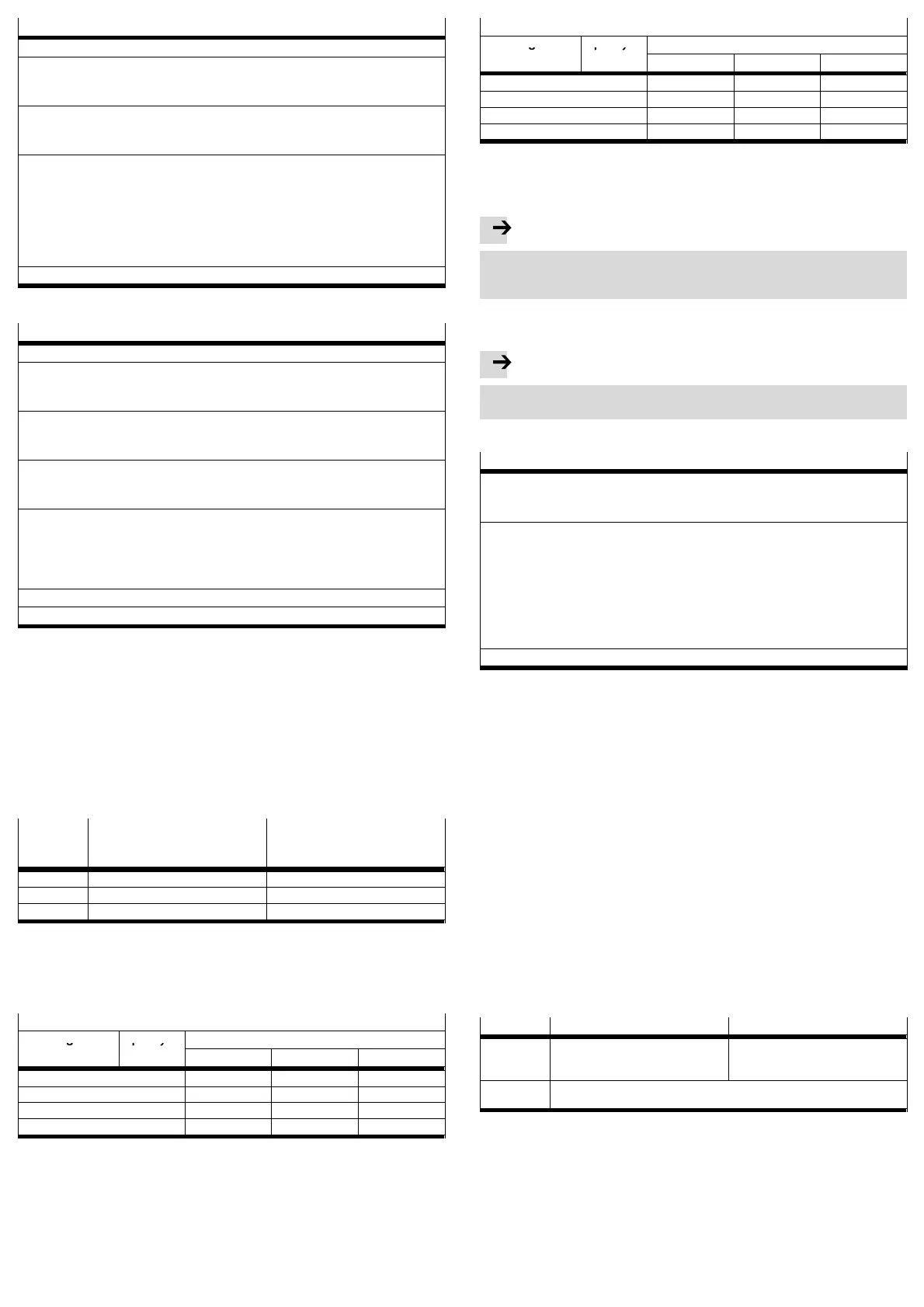
VPPM−...C1 Output pressure with
Signal 1 % FS
1)
Output pressure with
Signal
100 % FS
1)
2 bar type 0.02 bar 2 bar
6 bar type 0.06 bar 6 bar
10 bar type 0.1 bar 10 bar
1) FS = Full scale:
(1 % FS = 0.1 V or 4.16 mA / 100 % FS = 10 V or 20 mA)
Output pressure: 0 V or 4 mA creates an output pressure of 0 bar
Fig.30
Select a suitable parameter set:
Recommended parameter sets VPPM−... Sizes 1/8"
Tube length
1)
Open sys Output values in ml
tem
0 ... 100 100 ... 1000 > 1000
0 m 3 3 2 1
1 m 3 3 2 2
3 m 3 3 3 2
5 m 3 3 3 2
1) with tubing inner diameter 6 mm for 1/8" or 8 mm for 1/4"
Fig.31
Recommended parameter sets VPPM−... Sizes 1/4"
Tube length
1)
Open sys Output values in ml
tem
0 ... 500 500 ... 2000 > 2000
0 m 3 1 2 3
1 m 3 1 2 3
3 m 3 2 3 3
5 m 3 3 3 3
1) with tubing outer diameter 8 mm or 10 mm
Fig.32
7 Operation
Note
When switching off the VPPM..., make sure that first the setpoint value is set
to 0 V or 4 mA, then the supply pressure, then the setpoint value and finally the
supply voltage are switched off.
Resetting the VPPM−...C1 to the factory setting
(also if the security code cannot be found)
Note
By resetting to factory setting, the current settings are lost.
·If needed, note down these settings before resetting.
· Proceed as follows:
Reset the VPPM−...C1
1. Press and hold down the UP, DOWN and EDIT buttons.
2. Switch on the operating voltage.
3. Then release the buttons.
[ALL] flashes.
4. Select the parameters which you wish to reset to the factory setting with the
UP and DOWN buttons.
[Out] flashes: All output parameters are reset.
[In] flashes: All input parameters are reset.
[All] flashes: All input and output parameters as well as the security code are
reset.
5. Press the EDIT button in order to reset the selected parameters.
The VPPM−...C1 is then in the RUN mode again.
Fig.33
8 Service and maintenance
Cleaning:
· Switch off the following sources of energy before cleaning the exterior of the
device:
Operating voltage
Compressed air
·If the VPPM−...C1 is dirty, clean the exterior with a soft cloth.
The permitted cleaning agents are mild soapy water (max. + 50 °C) or all non−
abrasive media.
9 Disassembly
Disassembling:
· Switch off the following sources of energy:
Operating voltage
Compressed air
· Disconnect the relevant connections on the VPPM−...C1.
· Remove the VPPM−...C1 from the mounting surface/H−rail.
10 Accessories
For accessories, see www.festo.com\catalogue
11 Safety setting
Wire break Voltage type Current type
Setpoint
value
Output pressure drops to 0 bar. The last value is saved. The output
pressure is maintained but not regu
lated.
Supply volt
age
The last value is saved. The output pressure is maintained but not regulated. In
the medium term the pressure at the output can increase or diminish.
Fig.34

 Loading...