6.5 Configuring the VPPM−...C1
Editing the pressure range and the arrangement of the setpoint value display
1. In order to activate the EDIT mode, press the EDIT button.
Only with active security locking − [Lock] flashes:
2. Press the UP/DOWN button until the desired security code is set and confirm
by pressing the EDIT button.
[Out] flashes.
3. Press the UP/DOWN button until [In] flashes in the display, then press the
EDIT button.
[min] flashes.
Editing the pressure regulation range:
4. Set the minimum pressure value with the UP/DOWN buttons, then press the
EDIT button.
[max] flashes.
5. Set the maximum pressure value with the UP/DOWN buttons, then press the
EDIT button.
The current setpoint value display type flashes.
Either [mA] or [V] blinks, depending on the variant of the VPPM−...C1
or in percent blinks [%]
or [kPa], [psi] or [bar] blink, depending on the unit set in the SPEC menu.
Configuring the setpoint value display
6. Set the desired display type using the UP/DOWN buttons, then press the EDIT
button.
The VPPM−...C1 is then in the RUN mode again.
Fig.22
Configuring the switching output (Out)
Warning
Depending on the functions of the machine/system, the manipulation of signal
statuses can cause serious injury to human beings and material damage.
· Note that if the switching characteristics of the switching outputs are modi
fied in the EDIT mode, the new status will be effective immediately.
· Define the desired switching characteristics of switching output D3.
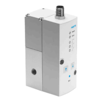
Switching points (SP...) and hysteresis (Hy)
With setting SP.O.
SP.O. signal
U [V]
p [bar]
t
t
Hysteresis
Actual value
Setpoint value
Fig.23
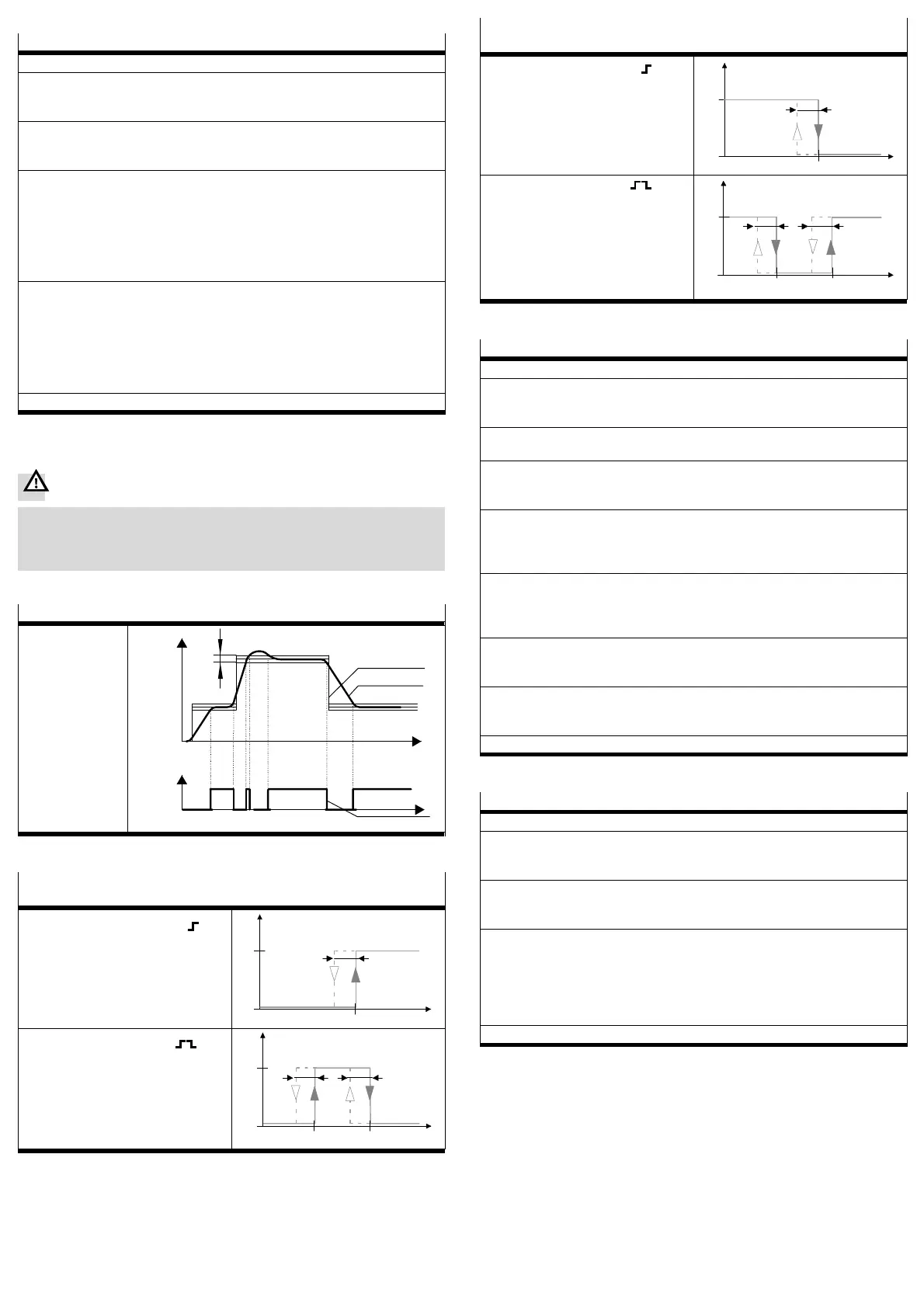
Switching points (SP...) and hysteresis (Hy) with NO setting (normally open
contact)
With threshold
value comparator setting
P
1
0
Hy
OUT
SP
With window
comparator setting
Hy Hy
P
1
0
OUT
SP
min.
SP
max.
Fig.24
Switching points (SP...) and hysteresis (Hy) with NC setting (normally closed
contact)
With threshold
value comparator setting
P
1
0
SP
Hy
OUT
With window
comparator setting
P
1
0
OUT
SP
min.
SP
max.
Hy
Hy
Fig.25
Configuring the switching output
1. In order to activate the EDIT mode, press the EDIT button.
Only with active security locking: [Lock] flashes.
2. Press the UP/DOWN button until the desired security code is set and confirm
by pressing the EDIT button.
[Out] flashes.
3. Press the EDIT button.
The current switching characteristic flashes.
4. Select the desired switching characteristic (threshold value/window compara
tor or S.P.O.) with the UP/DOWN button and confirm with the EDIT button.
With switching function Threshold Value/Window Comparator:
[SP] or [SP] [
min
] flashes.
5. Set the switching point (SP or SP
min
) with the UP/DOWN button and confirm
with the EDIT button.
With window comparator" switching function:
[SP] [
max
] flashes
6. Set the switching point (SP
max
) with the UP/DOWN button and confirm with
the EDIT button.
[HY] flashes.
7. Set the hysteresis (HY) with the UP/DOWN button and confirm with the EDIT
button.
[NO] or [NC] flashes.
8. Set the switching characteristic (NO/NC) with the UP/DOWN button and con
firm with the EDIT button.
The VPPM−...C1 is then in the RUN mode again.
Fig.26
Forcing the input
1. In order to activate the EDIT mode, press the EDIT button.
Only with active security locking: [Lock] flashes.
2. Press the UP/DOWN button until the desired security code is set and confirm
by pressing the EDIT button.
[Out] flashes.
3. Press the UP/DOWN button until [Force] flashes in the display, then press the
EDIT button.
[Force] flashes.
4. The set value can now be edited by pressing the UP and DOWN buttons.
Caution
Please note: the controller will apply the new set value immediately.
5. By pressing the EDIT button you can exit the Force mode. The analogue volt
age and current values of the input still apply.
The VPPM−...C1 is then in the RUN mode again.
Fig.27

 Loading...