12 Eliminating malfunctions
Cause Error display
Limit value not reached (setpoint value)
Limit value exceeded (setpoint value)
ER.09
ER.10
Undervoltage in the 24 V operating voltage
Overvoltage in the 24 V operating voltage
Hardware error
Temperature range exceeded in VPPM−...C1
ER.05
ER.26
ER.01
ER.28
Fig.35
Malfunction
Possible cause Remedy
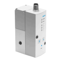
VPPM−..C1 notre
acting
Supply voltage not applied, POWER LED
does not light up
· Check connection of the
24 V DC power supply
Set value voltage or set value current not
applied
· Check controller
· Check connection
VPPM−... C1 defective Send the device to Festo for re
pairs.
Flow rate too low Restriction of the flow cross section due to
connection design (swivel fittings).
· Use an alternative connec
tion
Pressure in
creasetoo slow
Large cylinder volume and long tubing · Select different parameter
set
· Use larger nominal size
VPPM−...C1
Pressure constant
despite modified
setpoint specifi
cation
Supply cable breakage (the last output
pressure set is maintained but not regu
lated. In the medium term the pressure
at the output can increase or diminish).
Supply pressure P1 too low
· Replace power supply cable
· Increase supply pressure
UP/DOWN
buttons on the
VPPM−...C1 do not
react.
Voltage is present at digital inputs D1 and
D2.
· Apply 0 V DC to digital in
puts D1 and D2.
Fig.36
13 Technical data
General data
Design
Propor tional pressure regulator
Mounting position Any, preferably horizontal
(display components facing upwards)
Medium Filtered, unlubricated compressed air (grade
of filtration min. 40 m), no condensation
permissible.
Protection class IP 65 when mounted, with tightened mount
ing screws, in connection with plug socket
according to Accessories".
Perm. temp. range
Ambient
Medium
Storage
[°C]
0 ... +50
+10 ... +50
10 ... +70
Vibration and shock
Vibration
Shock
The following data does not apply to
mounting the VPPM... to the angle bracket
VAME−P1−A.
Tested according to DIN/IEC 68/EN 60068
part 2−6;
for wall mounting:
0.35 mm path at 10 ... 60Hz,
5g acceleration at 60 ... 150Hz
Test e d according to DIN/IEC 68/EN 60068 part
2−27;
for wall mountin g:
±30 g at 11 ms duration; 5 shocks per direction
Materials
Housing
Cap
Seals
Lubrication
Al wrought alloy
PAXMD6−GF50/gr−P, PA6−GB20,GF10/gr−P
NBR
Silicone−free
Weight [g] 1/8": 400
1/4": 560
Fig.37
Pneumatics data 2 bar type 6 bar type 10 bar type
Pressure ranges
Perm. supply pressure
Regulation range
[bar]
0 ... 4
0,02 ... 2
0 ... 8
0,06 ... 6
0 ... 11
0,1 ... 10
Supply pressure p1 at least 1 bar over output
pressure p2
Total leakage when new [l/h] < 5
Ports G1/8" (1/8 NPT), G1/4" (1/4 NPT)
Nominal size
Pressurisation
Exhaust
[mm]
with 1/8": 6
with 1/4": 8
with 1/8": 4.5
with 1/4": 7
Fig.38
Electrics data 2 bar type 6 bar type 10 bar type
Electrical connection Pin contact M12x1, 8−pin
Perm. operating voltage [V DC] 21.6 ... 26.4 V DC (perm. residual ripple
max. 10 %)
Max. electrical power consumption [W] 7
Power rating of digital switching out
put D3 (PIN 8 in el. connection)
[mA]
Max. 60
Max. perm. supply and signal line
length
[m]
10
Overall accuracy
Standard (2 %) +0.5 x Hysteresis
Class S1 (1 %) +0.5 x Hysteresis
[bar]
0.045
0.025
0.135
0.075
0.225
0.125
Hysteresis 0.5 % Full scale
Voltage boy VPPM−...−V1.−...C1
Setpoint variable
Input resistance(setpoint value)
Load of actual value output
Current type VPPM−..−A4.−...C1
Setpoint variable [mA]
Input resistance(setpoint value)
Load of actual value output []
[V DC]
[k]
[k]
[m A]
[ ]
[ ]
0 ... +10
10
min. 2
4 ... 20
250
Max. 500
Electromagnetic compatibility (EMC)
interference emission and resis
tance
See declaration of conformity
è www.festo.com
CE conformity for industrial installations
fulfilled.
Fig.39

 Loading...