 Need help?
Do you have a question about the FG Wilson OLYMPIAN 4001E Series and is the answer not in the manual?
Precautions and actions regarding fire and explosion hazards.
Safety guidelines for electrical operation and maintenance.
Procedures for providing first aid in case of electric shock.
Identifies and describes various control systems and their main components.
Describes protective circuits and shutdown conditions for the 1001 Series.
Protective circuits and shutdown conditions for 2001, 4001, 4001E systems.
Protective circuits and shutdown conditions for PowerWizard systems.
Troubleshooting steps for engine failing to start.
Troubleshooting for engine stopping due to various conditions.
Troubleshooting for engine failing to start on PowerWizard panels.
Troubleshooting for alarms and engine stops on PowerWizard panels.
This document serves as an operator's manual for a generating set, providing guidance on its operation, safety, and basic maintenance. It is designed to assist operators with starting, stopping, and general use of the generating set, while more in-depth technical details for installation, maintenance, and troubleshooting are covered in separate Technical Operation and Maintenance, Engine, and Alternator Manuals intended for qualified technicians.
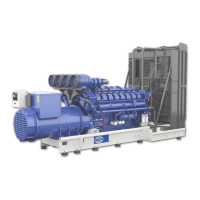
The generating set is a heavy-duty industrial unit engineered for superior performance and reliability. It arrives ready for operation, requiring only the addition of coolant, fuel, and battery acid. Each unit is uniquely identified by a rating plate, typically on the alternator housing, which provides essential information such as model and serial numbers, output characteristics (voltage, phase, frequency, kVA, kW), and rating type. This information is crucial for ordering spare parts and for service or warranty work.
At its core, the generating set is powered by a reliable diesel engine, specifically designed for generator applications. These engines are heavy-duty industrial types, either 4-stroke or 2-stroke compression ignition, and come equipped with all necessary accessories for dependable power supply. The engine's electrical system operates on either 12 or 24 volts DC, depending on the unit's size. Cooling is managed by a system comprising a radiator, a high-capacity pusher fan, and a thermostat, while the alternator has its own internal fan for cooling.
The engine and alternator are coupled and mounted on a robust steel baseframe. Most sets include a fuel tank providing approximately 8 hours of operation at full load, with an option for an extended 24-hour capacity tank. Vibration isolators are fitted between the engine/alternator feet and the baseframe to minimize vibration transmission to the foundation. For larger models, the engine/alternator is rigidly mounted, and vibration isolators are supplied separately for installation between the baseframe and the foundation. An exhaust silencer is provided for installation to reduce engine noise and direct exhaust gases safely.
The generating set incorporates various control systems and panels to manage its operation, output, and protection against malfunctions. These systems include the 1001 Series Keystart, 2001 Series Autostart, 4001 Series Deluxe Autostart, 4001E Series Enhanced Deluxe Autostart, and PowerWizard Autostart Systems. Specialized systems may be installed for specific applications, with separate documentation provided.
Each control system comprises three main components: a control panel, an engine interface module (EIM), and an alternator output circuit breaker. The control panel facilitates starting, stopping, monitoring, and automatic shutdown in critical conditions like low oil pressure or high engine coolant temperature. The EIM is a sealed, engine-mounted module with switching relays for the starter motor solenoid, glow plug, and fuel solenoid, each protected by individual fuses. LEDs on the EIM indicate when each circuit is energized. EIM models vary (12 volt EIM SR, 12 volt EIM Plus, 24 volt EIM SR, 24 volt EIM Plus) depending on the generating set's kVA rating. The alternator output circuit breaker protects the alternator from overload or short circuit by disconnecting the load and provides a means to switch the generating set's output.
Panel equipment for 1001, 2001, 4001, and 4001E Series includes an AC Voltmeter with a selector switch to monitor voltage between phases or phase and neutral, an AC Ammeter with a selector switch to monitor current, a Frequency Meter, an Hours Run Meter for maintenance tracking, an Engine Water Temperature Gauge, and an Engine Oil Pressure Gauge. Fault Indicator Lamps illuminate to signal protective circuitry activation, with red lamps for shutdowns and red or amber for alarms. A Lamp Test Pushbutton allows testing of fault lamps and resetting alarms. The 1001 Series features a Key Switch for starting, stopping, and resetting protection circuitry.
For 2001, 4001, and 4001E Series, a Control Switch offers "RUN," "STOP," and "AUTO" positions for manual or automatic operation. An Emergency Stop Pushbutton provides immediate shutdown and inhibits starting until released. A Thermostart Preheat Button powers the preheat circuit if fitted.
PowerWizard control panels feature a Display Screen for information and event logs, AC Overview and Engine Overview keys for navigating parameters, Yellow Warning and Red Shutdown Lights for active and acknowledged warnings/shutdowns, and an Alarm Acknowledgment Silence button to silence horns and manage flashing lights. Navigation is via UP, DOWN, RIGHT, LEFT, ESCAPE, and ENTER keys for menus and setpoint adjustments. A separate Emergency Stop Pushbutton functions similarly to other series. Display preferences like contrast, backlight, pressure units, temperature units, volume units, and language can be adjusted.
For automatic standby power, Load Transfer Panels (ATI Series Intelligent Transfer Panels and TC Series Compact Transfer Panels) are used. These panels detect mains failure, signal the generator to start, transfer the load, and switch back to mains upon restoration. Status panels on these units feature indicator LEDs for "Mains Available," "Mains on Load," "Generator on Load," and "Generator Available." Controls include a Mode Selector Switch with "AUTOMATIC MODE," "TEST WITHOUT LOAD," and "TEST WITH LOAD" positions. A Manual Retransfer Function, if enabled, allows operators to control load retransfer timing.
Maintenance features include Battery Trickle Chargers to maintain battery charge, various heaters (immersion, alternator anti-condensation, panel anti-condensation) for cold or humid environments, and Electric Fuel Transfer Pumps for moving fuel from bulk storage to the day tank. Additional meters/gauges like 3 Ammeters, Kilowatt Meter, Combined Tachometer and Frequency Meter, Lube Oil Temperature Gauge, and Battery Trickle Charger Ammeter can be fitted. Speed/Voltage Control options allow adjustment of generator speed or voltage. Alarm Signalling options include panel-mounted or loose alarm sirens with mute pushbuttons, and volt-free contacts for external alarm systems. Automatic Preheat Control automates glow plug operation. Remote Annunciator Panels provide repeat indicators for shutdown and alarm fault lamps, with options for a Normal/Run switch and Emergency Stop Pushbutton. The X100 AMF Upgrade integrates automatic mains failure functionality into the control panel, adding a status display panel with indicators for Mains Available, Mains on Load, Generator Available, and Generator on Load, plus a test switch. Digital Instrumentation is an option that replaces analogue AC instruments with digital displays for voltage, frequency, and current, with LED indicators for phase measurement.
Safety is paramount, with warnings against operating with removed guards, touching hot surfaces, or electrically energized parts. Personnel must be authorized and trained, wear protective clothing, and be aware of moving parts. Chemical safety includes precautions against ingesting or skin contact with fuels, oils, coolants, lubricants, and battery electrolyte. Noise warnings emphasize the need for ear protection. Electrical safety requires proper grounding, avoiding contact with live parts, and using appropriate fire extinguishers. First aid instructions for electric shock are provided, detailing steps for opening the airway, breathing, circulation, and recovery position.
Maintenance is crucial for longevity, with records recommended for efficient programming. The set should be kept clean, free of liquid accumulation, and any damaged acoustic material replaced. Battery removal and fitting instructions emphasize safety due to hazardous materials and explosive gases, including proper disconnection, inspection for damage, covering terminals during transport, and correct re-attachment of cables.
 General
| Model | OLYMPIAN 4001E Series |
|---|---|
| Type | Portable Generator |
| Fuel Type | Diesel |
| Starting System | Electric Start |
| Frequency | 50 Hz |
| Voltage | 230 Volts |
| Run Time | Varies with load |


 To Next Page