AP SERIES
970-292 Revised 5-12
AP SERIES
Table of Contents
Model Nomenclature ..................................................................................................................1
Initial Inspection............................................................................................................................2
General Description .....................................................................................................................2
Moving and Storage....................................................................................................................2
Safety Considerations .................................................................................................................2
Location............................................................................................................................................2
Installation.......................................................................................................................................2
Condensate Drain.........................................................................................................................3
Duct System....................................................................................................................................3
Piping ................................................................................................................................................3
Electrical...........................................................................................................................................4
Thermostat Connections ...........................................................................................................4
Safety Devices & the UPM Controller....................................................................................5
Electric Heater Package Option...............................................................................................6
Sequence of Operation Single Stage Units.........................................................................7
Sequence of Operation Two-Stage Units ............................................................................7
Well Water Systems .....................................................................................................................7
Installation of Pressure Regulating Valves ..........................................................................7
Cooling Tower / Boiler Application........................................................................................7
Earth Coupled Systems...............................................................................................................8
System Checkout ..........................................................................................................................8
Unit Start-Up...................................................................................................................................8
Maintenance...................................................................................................................................8
Wiring Diagrams ...........................................................................................................................9
Trouble Shooting .......................................................................................................................13
Unit Check Out............................................................................................................................14
Operating Pressures & Temperatures.................................................................................15
MODEL NOMENCLATURE
SERIES:
AP-AQUARIUS II
NOMINAL CAPACITY:
VOLTAGE DESIGNATION:
1 - 208/1/60 & 230/1/60
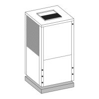
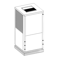
CABINET CONFIGURATION:
VT - VERTICAL
HZ - HORIZONTAL
CF - COUNTERFLOW
HEAT EXCHANGER MATERIAL:
C - COPPER
N - CUPRO-NICKEL
SUPPLY AIR LOCATION:
T - TOP (VT ONLY)
E - END BLOW (HZ ONLY)
B - BOTTOM (CF ONLY)
RETURN AIR LOCATION:
L - LEFT
R - RIGHT
B - BACK
F - FRONT
WATER CONNECTION
LOCATION:
F - FRONT
AP 049 -1 VT C-F L T