8
InstallatIon
4.2: Electrical connection
1. Switch o the mains voltage (disable the fuse) or disable the
power supply.
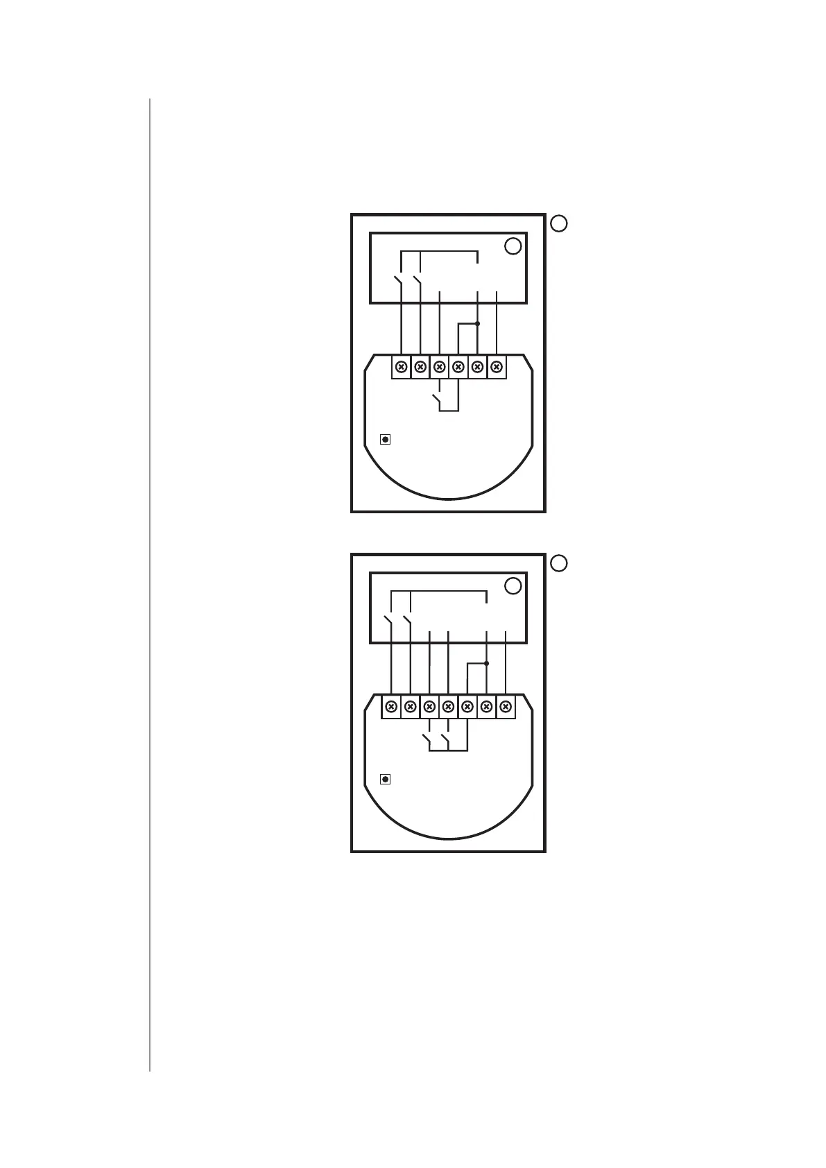
2. Connect with one of the diagrams below:
B
IN
L
24-30V DC
100-240V AC
NS1 S2
Q
SMART MODULE
FGS-214
Diagram 1: Example connection of Smart Module
B
INQ1
L
24-30V DC
NS1 S2
Q2
DOUBLE
SMART MODULE
FGS-224
100-240V AC
Diagram 2: Example connection of Double Smart Module
3. Verify correctness of connection.
4. Tighten the terminal screws using PH1 screwdriver.
5. If the device fully assembled, switch on the mains voltage or
enable the power supply.
6. The LED light means the device is powered.
7. Add the device to the Z-Wave network (see the next chapter).
 Loading...