EasyManua.ls Logo

Field Controls CAS-34U - User Manual

Field Controls CAS-34U
16 pages
Print Icon
To Next Page IconTo Next Page
Loading...
www. eldcontrols.com
Please retain these instructions after installation.
This device MUST be installed by a quali ed agency in accordance with the manufacturer's installation instructions. The de nition of
a quali ed agency is: any individual,  rm, corporation or company which either in person or through a representative is engaged
in, and is responsible for, the installation and operation of HVAC appliances, who is experienced in such work, familiar with all the
precautions required, and has complied with all the requirements of the authority having jurisdiction.
READ THESE INSTRUCTIONS CAREFULLY AND COMPLETELY BEFORE PROCEEDING WITH THE INSTALLATION.
Installation Date:
Installed By: Phone:
COMBUSTION AIR SYSTEM
Model: CAS-34U
ITEMS INCLUDED IN KIT:
1 - Motorized Blower
2 - Mounting Brackets
1 - 4" x 6" Pipe Increaser Fitting
1 - Instruction Sheet
1 - 4” Intake Air Hood
1 - 6” Ori ce Ring
WARNING
CONNECTIONS TO MULTIPLE APPLIANCES MUST FOLLOW INSTALLATION INSTRUCTION WIRING DIAGRAMS.
P/N 780107600 Rev B 05/23
Question and Answer IconNeed help?

Do you have a question about the Field Controls CAS-34U and is the answer not in the manual?

Overview

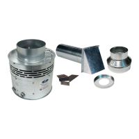
The CAS-34U is a combustion air system designed to provide necessary combustion air for various heating appliances. It is a universal system compatible with oil, natural gas, or LP burning furnaces, water heaters, and boilers. The unit operates with either 120VAC or 24VAC control systems and can also be used with 30mV standing pilot gas water heaters when combined with a CK-20 series control kit. For additional 120V or 24V controlled appliances, a CAC-120 or CAC-24 control kit (one per additional appliance) is required.

Function Description:

The CAS-34U mechanically draws outside air into the structure and disperses it near the combustion air intake of the appliance(s). When the thermostat or aquastat calls for heat, the CAS-34U unit activates. Once the fan reaches operating speed and sufficient airflow is established at the inlet, an internal air pressure switch closes, completing the circuit to allow the burner to fire. In power-vented systems, both the venter and CAS-34U activate simultaneously. After they reach operating speed, a pressure switch in the power venter control closes, allowing the appliance to fire. When the heating requirement is met, the thermostat circuit opens, deactivating the burner and the CAS-34U unit. For power-vented systems with a post-purge device, the power venter and CAS-34U will continue to operate for a period after burner shutdown to clear residual flue gases from the vent system.

Important Technical Specifications:

General:

  • Model: CAS-34U
  • Power Input: 120VAC, 60Hz
  • Internal Motor: 0.8A, 2600 RPM (maximum loaded speed)
  • L1 Terminal (Idle Current): 18.25mA (no call for heat, no signal on M terminal)
  • M Terminal (Input Signal): 120VAC, 5mA (trigger voltage above 89.6VAC)
  • Voltage Selection Switch: Sets the desired voltage on the T1 terminal.

For Oil Appliances (120VAC nominal, switch in 120VAC position):

  • T1 (Minimum Operating Voltage): 89.6VAC
  • T1 (Drop Out Voltage): 58.4VAC
  • T2: Must be connected to neutral in reference to T1 supply voltage.
  • T1 & T3 (Maximum Full Load Conditions): 120VAC, 60Hz, FLA 9.8A, LRA 58.8A (1/2HP).

For Gas Appliances (24VAC, switch in 24VAC position):

  • T1 (Minimum Operating Voltage): 18.75VAC
  • T1 (Drop Out Voltage): 13.8VAC
  • T2: Must be connected to 24VAC common in reference to T1 supply voltage.
  • T1 & T3 (Full Load Conditions): 3.3A up to 5A (typical gas appliance 3.3A or less, Class II).

Ductwork Sizing (Maximum Equivalent Feet of Installation):

The system's performance depends on the total input of the appliance (Oil gph / Gas BTU) and the duct configuration (6" Duct and 6" Intake Air Hood, 4" Duct and 4" Intake Air Hood, or 4" Duct and Hood with Orifice Ring). The CAS-34U has a High/Low motor speed control switch, affecting the maximum equivalent feet.

  • For 0.50-0.75 gph Oil / 50,000-100,000 BTU Gas:

    • 6" Duct and 6" Intake Air Hood: 300 feet (HI/LOW)
    • 4" Duct and 4" Intake Air Hood: 300 feet (HI/LOW)
    • 4" Duct and Hood w/ Orifice Ring: 300 feet (HI/LOW)
  • For 2.00 gph Oil / 300,000 BTU Gas:

    • 6" Duct and 6" Intake Air Hood: 300 feet (HI), 53 feet (LOW)
    • 4" Duct and 4" Intake Air Hood: 16 feet (HI), N/A (LOW)
    • 4" Duct and Hood w/ Orifice Ring: N/A (HI/LOW)
  • For 3.25 gph Oil / 450,000 BTU Gas:

    • 6" Duct and 6" Intake Air Hood: 56 feet (HI), N/A (LOW)
    • Other configurations: N/A

Equivalent Feet for Intake Pipe Fittings:

  • 90° Elbow: 7 feet (4" diameter), 11 feet (6" diameter)
  • 45° Elbow: 4 feet (4" diameter), 5 feet (6" diameter)

Usage Features:

Installation:

  • Placement: The motorized CAS-34U unit should be located in a dry, flat, horizontal area, ideally within 3 feet of the appliance's combustion air intake. Mounting brackets are provided for securing the unit to a solid structure (wall, column, or appliance side). The unit can be suspended off the floor using brackets to avoid wet or damp conditions.
  • Intake Air Hood Location: The intake air hood must be located on an outside wall, maintaining minimum clearances from other intake and exhaust vents as per National Fuel Gas Code, ANSI Z223.1, manufacturer's recommendations, and local codes. It should be at least 10 feet from a power-vented exhaust outlet and at least 18 inches above ground level (or above snow line, whichever is greater). Avoid locations near pollutant sources (auto exhaust, dryer exhaust, fuel-burning appliances, garbage bins, barbecue grills) and do not use crawl spaces, basements, or attics as air sources.
  • Duct Installation: Connect duct pipe from the CAS-34U unit to the intake air hood. If using 4" pipe, attach the provided 4" x 6" Pipe Increaser Fitting to the CAS-34U unit. Ductwork should be supported with mounting straps from floor joists, walls, or other solid structures, keeping it out of passageways. A minimum of 12 feet of pipe is recommended to temper outside air.
  • Wiring: The unit must be grounded and wired according to the National Electrical Code and local codes, protected by a 15-ampere over-current circuit device. Ensure wiring does not contact heat sources. The voltage selection switch must be set to the correct position for the application (120V for oil, 24V for gas). Wiring diagrams are provided for various applications, including chimney vent and power vent systems for single and multiple oil or gas appliances.

Maintenance Features:

Annual Inspection:

  1. System Operation: Annually inspect the system to ensure proper operation. Verify that the fan activates when there's a call for heat and deactivates when the heating requirement is satisfied.
  2. Power Disconnection Test: Disconnect power to the CAS-34U unit. The unit should not run, and the appliance should not fire in this condition.
  3. Ductwork Integrity: Inspect the duct pipe for cracks and ensure it is securely fastened to the CAS-34U unit and intake air hood. The CAS-34U will prevent the appliance(s) from firing if there is inadequate airflow into its inlet.
  4. Clear Obstructions: Clear any obstructions from the intake air hood inlet and the CAS-34U unit outlet.
  5. Fan Blade Cleaning: Periodically clean the fan blade chamber. Disconnect power, remove the duct pipe, then remove the top pan to access and clean the fan housing. Reattach the top pan, reconnect the duct pipe, and restore power.

Troubleshooting:

  • Burner does not fire when thermostat calls for heat:
    • Check that the draft tube is securely fastened to the air pressure switch and is not blocked.
    • Verify continuity across pressure switch terminals when the system is operating.
    • Check wiring connections between the air pressure switch and the appliance.
  • System does not activate when thermostat calls for heat:
    • Check if the relay closes when the thermostat calls for heat.
    • Check wiring connections.
    • Check the motor for unrestricted shaft rotation.
  • Exhaust gas odor:
    • Check the system draft level during operation.
    • Check the vent system on the appliance.
    • Check for negative pressure in the building.

Replacement Parts:

  • PCB Control Assy, CAS-34U: Part No. 602400200
  • Motor Assy, CAS-34U: Part No. 602400300
  • IAH-4 Intake Air Hood: Part No. 46292000
  • IAH-6 Intake Air Hood: Part No. 46293000
  • Pressure Switch, CAS-34U: Part No. 602400400

Field Controls CAS-34U Specifications

General IconGeneral
BrandField Controls
ModelCAS-34U
CategoryBoiler Supplies
LanguageEnglish