page 6
WIRING INSTRUCTIONS
Wire the CAS unit in accordance with the National Electric Code and applicable local codes. UNIT MUST
BE GROUNDED. Check the ground circuit to make certain that the unit has been properly grounded. The
wiring should be protected by an over-current circuit device rated at 15 amperes. CAUTION must be taken
to ensure that the wiring does not come in contact with any heat source. All line voltage and control circuits
between the CAS unit and the appliance MUST be wired in accordance with the National Electrical Code
for Class I wiring or equivalent.
Remove the wiring access cover to access the wiring terminals. Use the enclosed conduit connector(s) to
route the appropriate wires through the CAS housing. The incoming ground wire must be attached to the
green colored ground screw near the wire terminals. The following sections describe the most common
applications. The references to various series of control kits implies that any kit in that series may be used. If
further information or additional wiring diagrams are needed please consult Field Controls' technical support.
Black
White
White
White
Red
Red
Common
Common
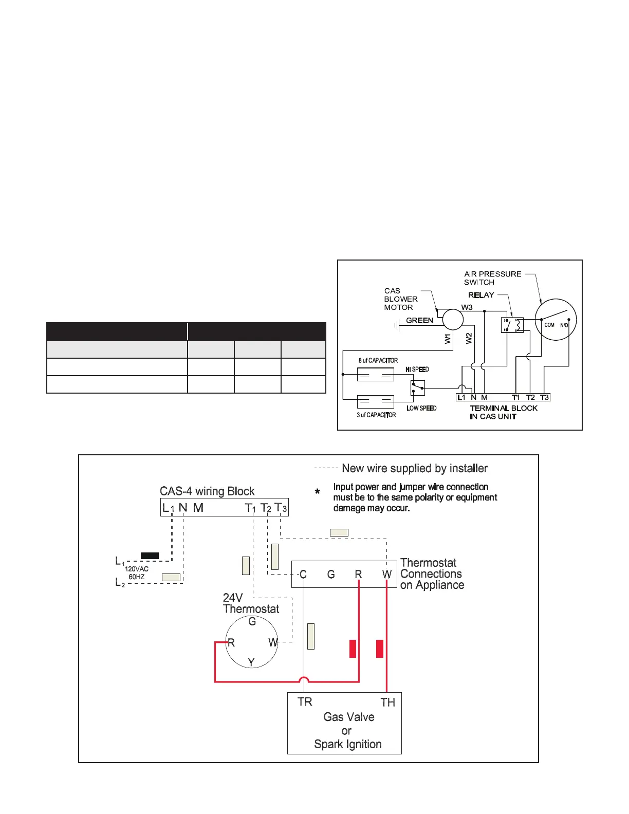
INTERNAL WIRING CONNECTIONS FOR THE CAS UNIT
Refer to Figure 4 for the internal wiring of the CAS-4 unit.
External Wiring Connections
Refer to Figures 5-12 for appropriate wiring method.
Figure 4
Figure 5- Chimney Vent Single 24V Furnace
WIRE KEY WIRE COLOR
MOTOR MANUFACTURER W1 W2 W3
McLean Engineering Black Blue Brown
All Others Brown Black Blue