page 5
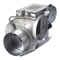
PLACEMENT OF THE CAS UNIT
The motorized CAS unit should be located on a flat horizontal
surface within the same space as the appliance and within
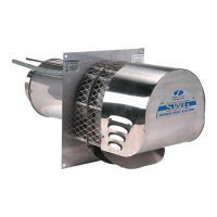
3' of the combustion air intake as possible. Two mounting
brackets are provided for securing the unit against a solid
structure, such as a wall, column, or the side of the appliance
itself. Use the included screws to attach the brackets to the
CAS housing as shown in Figure 1. Secure the brackets to a
solid structure with appropriate fasteners. It is not required to
use the brackets as long as the unit is located so that it may
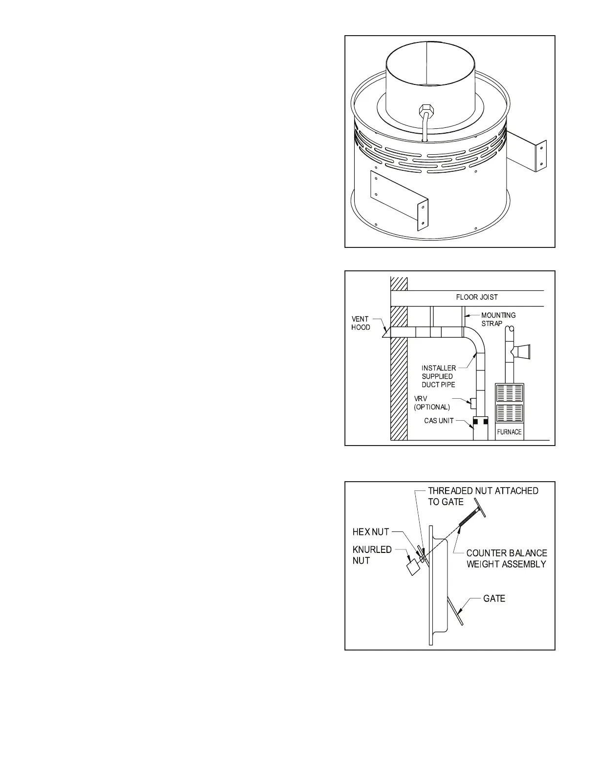
not be bumped, moved, or tipped over. The optional Vacuum
Relief Valve (VRV) should be placed directly on the air inlet of
the CAS unit if using 6". (See Figure 2) Refer to Diagram A to
determine if the VRV is needed. The VRV should be oriented
so that the axis of the swinging gate is horizontal.
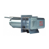
ASSEMBLING THE WEIGHTS ON THE VRV
Refer to Figure 3 to assemble the weight assembly, hex nut,
and knurled nut to the VRV gate. After the weight is correctly
positioned, tighten the hex nut against the gate to prevent the
weight assembly from moving during operation.
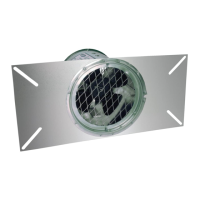
INTAKE AIR HOOD LOCATION
The 4" galvanized vent hood should be located on an
outside wall maintaining minimum clearances to other intake
and exhaust vents in accordance with the National Fuel Gas
Code, ANSI Z223.1, manufacturer's recommendations and/
or local codes which are applicable. The hood should be
located at least 10' from a power vented exhaust outlet and
should be on the same wall. The intake air hood should be a
minimum of 1' above grade or snowlines where applicable.
INSTALLATION OF INTAKE AIR HOOD
After determining the location of the vent hood, cut a 4
1
⁄2" round or square hole in the wall. Insert the vent hood
and secure with appropriate fasteners. Take precautions
to avoid interference with wiring or other plumbing in the
wall to be cut.
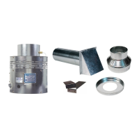
INSTALLATION OF DUCT
Refer to Diagram A or B to determine what size pipe is
needed. Connect the duct pipe from the top of the CAS
unit to the Vent Hood in the wall. If using 4" diameter pipe
attach the provided 4" x 6" Pipe lncreaser Fitting to the top
of the CAS unit (or the VRV, if installed). The duct should
be supported with appropriate mounting straps from floor joists,
walls, or other solid structures. The straps should be placed so as to keep the ductwork out of passageways.
(See Figure 2) A minimum of 12' of pipe should be run to help temper outside air being drawn in. The VRV
may also be installed near the intake air hood and adjusted to mix room air with outside air to help temper
air in cold climates.
INSTALLATION
Figure 1
Figure 2
Figure 3
 Loading...