EasyManua.ls Logo

Field Controls FAN IN A CAN CAS4 - User Manual

Field Controls FAN IN A CAN CAS4
12 pages
Print Icon
To Next Page IconTo Next Page
Loading...
www. eldcontrols.com
Please retain these instructions after installation.
This device MUST be installed by a quali ed agency in accordance with the manufacturer's installation instructions. The de nition of
a quali ed agency is: any individual,  rm, corporation or company which either in person or through a representative is engaged
in, and is responsible for, the installation and operation of HVAC appliances, who is experienced in such work, familiar with all the
precautions required, and has complied with all the requirements of the authority having jurisdiction.
READ THESE INSTRUCTIONS CAREFULLY AND COMPLETELY BEFORE PROCEEDING WITH THE INSTALLATION.
Installation Date:
Installed By: Phone:
COMBUSTION AIR SYSTEM
MODEL: CAS-4
This product is designed for use with any natural gas or LP burning furnace, water heater, or boiler with a 24
VAC control system. The CAS-4 may be used with one 24V-controlled combustion heating appliance and one
30mV standing-pilot gas water heater with the use of an additional CK-20 series control kit. Additional 120V or
24V-controlled appliances may also be served by the CAS-4 with the addition of one CAC-120 or CAC-24 control
kit per each additional appliance (see note)*. The CAS unit mechanically draws air into a structure and disperses it
near the combustion air intake of an appliance. Refer to Diagrams A and B for guidance in setting up the CAS
system based on the size and length of the connecting ductwork and the input rating of the appliance.
ITEMS INCLUDED IN KIT:
1- Motorized Blower 1- 4" galvanized intake air Vent Hood
2- Mounting brackets to secure the CAS to a wall 2- Wire/conduit connectors
1- 4" x 6" Pipe Increaser Fitting 1- 6" Ori ce Ring
1- Instruction Sheet 1- High/Low Motor Speed Switch
P/N 46284600 Rev L 09/19
WARNING! CONNECTIONS TO MULTIPLE APPLIANCES MUST FOLLOW INSTALLATION INSTRUCTION
WIRING DIAGRAMS. FOR HELP CALL 1-800-742-8368.
*NOTE: The model CAS-4 design has recently been changed. Please note that there are di erences in construction,
operation, and installation of this CAS as compared to legacy product. Also, note that for multiple-appliance
installations, each additional appliance will require either a CAC-24 or CAC-120 control kit be provided for that
appliance. Installations with one heating appliance and one 30mV gas water heater will require an additional CK-20
series control kit in addition to the CAS-4.
Question and Answer IconNeed help?

Do you have a question about the Field Controls FAN IN A CAN CAS4 and is the answer not in the manual?

Overview

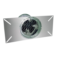
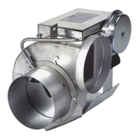
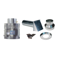
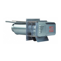
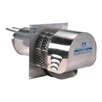
The Field Controls CAS-4 Combustion Air System is designed to provide combustion air for various heating appliances, including natural gas or LP burning furnaces, water heaters, and boilers, especially those with 24 VAC control systems. This device mechanically draws outside air into a structure and disperses it near the combustion air intake of the appliance, ensuring proper combustion and preventing negative pressure issues within the building.

Function Description:

The CAS-4 operates by activating in response to a call for heat from a thermostat (wall thermostat or aquastat). When energized, the CAS fan starts, and once sufficient airflow is established into the CAS inlet, an internal air pressure switch closes, completing the circuit to allow the burner to fire. For power-vented systems, the venter and CAS activate simultaneously, and a pressure switch in the power venter control closes to allow the appliance to fire. After the heating requirement is satisfied, the thermostat circuit opens, deactivating the burner and the CAS unit. In power-vented systems with a post-purge device, both the power venter and CAS may continue to operate for a period to purge remaining flue gases.

The system is versatile, capable of serving one 24V-controlled combustion heating appliance and one 30mV standing-pilot gas water heater with the addition of a CK-20 series control kit. For multiple appliances, additional 120V or 24V-controlled appliances can be served by adding a CAC-120 or CAC-24 control kit per appliance.

Important Technical Specifications:

  • Appliance Compatibility: Designed for natural gas or LP burning furnaces, water heaters, or boilers with a 24 VAC control system.
  • Control Kits:
    • CK-20 series control kit: Required for installations with one heating appliance and one 30mV gas water heater.
    • CAC-24 or CAC-120 control kit: Required for each additional 120V or 24V-controlled appliance in multiple-appliance installations.
  • Included Components:
    • 1 Motorized Blower
    • 2 Mounting brackets (for wall attachment)
    • 1 4" x 6" Pipe Increaser Fitting
    • 1 Instruction Sheet
    • 1 4" galvanized intake air Vent Hood
    • 2 Wire/conduit connectors
    • 1 6" Orifice Ring
    • 1 High/Low Motor Speed Switch
  • Ductwork: The system utilizes 4" or 6" diameter sheet metal duct pipe. The maximum equivalent length of duct pipe varies based on the appliance's firing rate and the selected motor speed (High/Low), as detailed in the sizing charts (Diagrams A and B) and Table 1.
  • Electrical: Unit must be grounded. Wiring should be protected by an over-current circuit device rated at 15 amperes. All line voltage and control circuits between the CAS unit and the appliance must be wired in accordance with the National Electrical Code for Class I wiring or equivalent.
  • Air Pressure Switch: An internal air pressure switch ensures proper airflow before allowing the burner to fire.

Usage Features:

  • Sizing and Setup: Installation requires careful sizing based on the appliance's maximum input firing rate (or total firing rate for multiple appliances) and the equivalent length of duct pipe. Diagrams A and B, along with Table 1, guide installers in selecting the appropriate duct diameter (4" or 6"), motor speed (High or Low), and whether to use the included 6" orifice ring for 4" duct installations.
  • High/Low Motor Speed Switch: The CAS-4 is equipped with a High/Low motor speed control switch, allowing for adjustment based on the application's requirements and ductwork configuration.
  • Orifice Ring: A 6" orifice ring is provided for use with 4" diameter duct pipe to optimize airflow characteristics for specific firing rates and duct lengths.
  • Placement: The motorized CAS unit should be located on a flat horizontal surface within the same space as the appliance and within 3 feet of the combustion air intake. Mounting brackets are provided for securing the unit to a wall, column, or the appliance itself.
  • Intake Air Hood Location: The 4" galvanized vent hood should be placed on an outside wall, maintaining minimum clearances to other intake and exhaust vents according to National Fuel Gas Code, ANSI Z223.1, manufacturer's recommendations, and local codes. It should be at least 10 feet from a power-vented exhaust outlet, on the same wall, and a minimum of 1 foot above grade or snowlines.
  • Duct Installation: A 4 ½" round or square hole is required for the vent hood. Duct pipe connecting the CAS unit to the vent hood should be supported with mounting straps. A minimum of 12 feet of pipe is recommended to temper outside air. All duct joints must be sealed.
  • Wiring Diagrams: Detailed wiring diagrams are provided for various configurations, including chimney vent single 24V furnace, power vent single 24V furnace, chimney vent 24V furnace and 30mV water heater with CK-20FV or CK-20FG, chimney vent 24V boiler, power vent single 24V boiler, chimney vent two 24V gas appliances with CAC-24, and one power venter two 24V gas appliances.

Maintenance Features:

  • Annual Inspection: The system should be inspected annually to ensure proper operation. This involves verifying that the fan activates with a call for heat and deactivates when the call is satisfied.
  • Safety Check: Disconnect power to the CAS unit and confirm that the unit does not run and the appliance does not fire, indicating proper safety interlock function.
  • Ductwork Integrity: Inspect the duct pipe for cracks and security to the CAS unit and vent hood. The CAS unit will prevent the appliance(s) from firing if inadequate airflow is detected.
  • Obstruction Clearance: Clear any obstructions from the inlet of the vent hood and the outlet of the CAS unit.
  • Fan Blade Cleaning: Periodically, the fan blade chamber may require cleaning. This involves disconnecting power, removing the duct pipe, detaching the top pan, cleaning the fan housing, and then reassembling.
  • Replacement Parts: A list of available replacement parts is provided, including:
    • Motorized Fan (Part Number: 46274100)
    • Pressure Switch Fxd for CAS-4TMR (Part Number: 511100200)
    • 24 VAC Relay for CAS-4 (Part Number: 46161400)
    • 120 VAC Relay for CAS-3,4 (Part Number: 46257300)
    • Replacement of parts requires disconnecting power and disassembling the unit. Technical support is available for assistance.

Field Controls FAN IN A CAN CAS4 Specifications

General IconGeneral
BrandField Controls
ModelFAN IN A CAN CAS4
CategoryFan
LanguageEnglish

Related product manuals