page 2
PRESSURE SWITCH SENSING TUBE INSTALLATION
1. Attach the
1
⁄4" tubing connector to the pressure tube on the SWG Venter.
(See Figure 3)
2. Connect the supplied
1
⁄4" aluminum tubing to the tubing
connector. Route the tubing to the CK- 61 junction box and
connect the tubing to the pressure switch. When routing the
tubing, avoid kinking the tubing by bending the tubing
too sharply.
3. For remote mounted CK-61 junction box, use a
1
⁄4" OD
copper, aluminum or plastic tubing and route the tubing to
avoid contact with any heat source.
Refer to the SWG Venter installation instructions for setting
system air ow.
SEE THE APPLIANCE MANUFACTURER’S INSTRUCTIONS FOR THE SPECIFIC LOCATION.
IF THE APPLIANCE MANUFACTURER DOES NOT SPECIFY A LOCATION, REFER TO FIGURE 5.
Figure 1
Figure 2
Figure 3
Figure 4
Figure 5
INSTALLATION
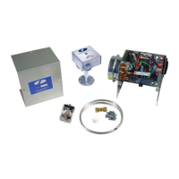
MOUNTING JUNCTION BOX
The junction box can be mounted at the venter or remotely mounted away
from the venter. (See Figure 1 & Figure 2)
1. Remove one of the knockouts from the side of the junction box where
the pressure switch is mounted. Install the exible conduit connector
onto the CK-61 junction box and secure with fastening nut. If remote
mounting the CK-61 junction box, mount the exible conduit connector
onto a 2” x 4” installer supplied junction box.
2. Fasten the exible conduit from the SWG Venter into the conduit
connector. Mount the CK-61 junction box or installer supplied junction
box onto the wall or oor joist without straining the exible conduit.
Fasten the CK- 61 junction box through the four dimpled locations on
the base of the box. (See Figure 3)
OIL FIRED SECONDARY SAFETY SWITCH (WMO-1)
Installation of a SECONDARY SAFETY SWITCH (WMO-1) is recommended
for detecting ue gas spillage from a blocked ue system and/or
inadequate draft.
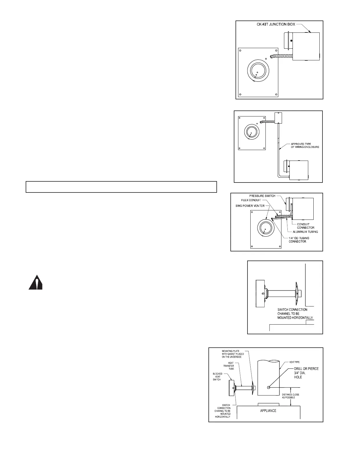
MOUNTING IN THE VENT PIPE
1. Drill or pierce a clean hole (about
3
⁄4” diameter) in the vent pipe near
the appliance outlet. (See Figure 5)
2. The heat transfer tube must have the ber gasket installed against the
mounting plate before attaching the unit to the vent pipe.
3. Insert the heat transfer tube with gasket into the
3
⁄4” diameter hole
placed in the vent pipe during step 1.
4. Secure the assembly to the vent pipe with a minimum of 4 sheet
metal screws. The channel must be mounted horizontally, unless
speci ed di erently by the appliance manufacturer. (See Figure 5)
CAUTION: Disconnect electrical power supply to the appliance when wiring the
blocked vent switch.
WARNING: Switch connection channel must be mounted horizontally,
unless speci ed di erently by the appliance manufacturer.