page 6 of 12
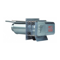
VENTER LOCATION
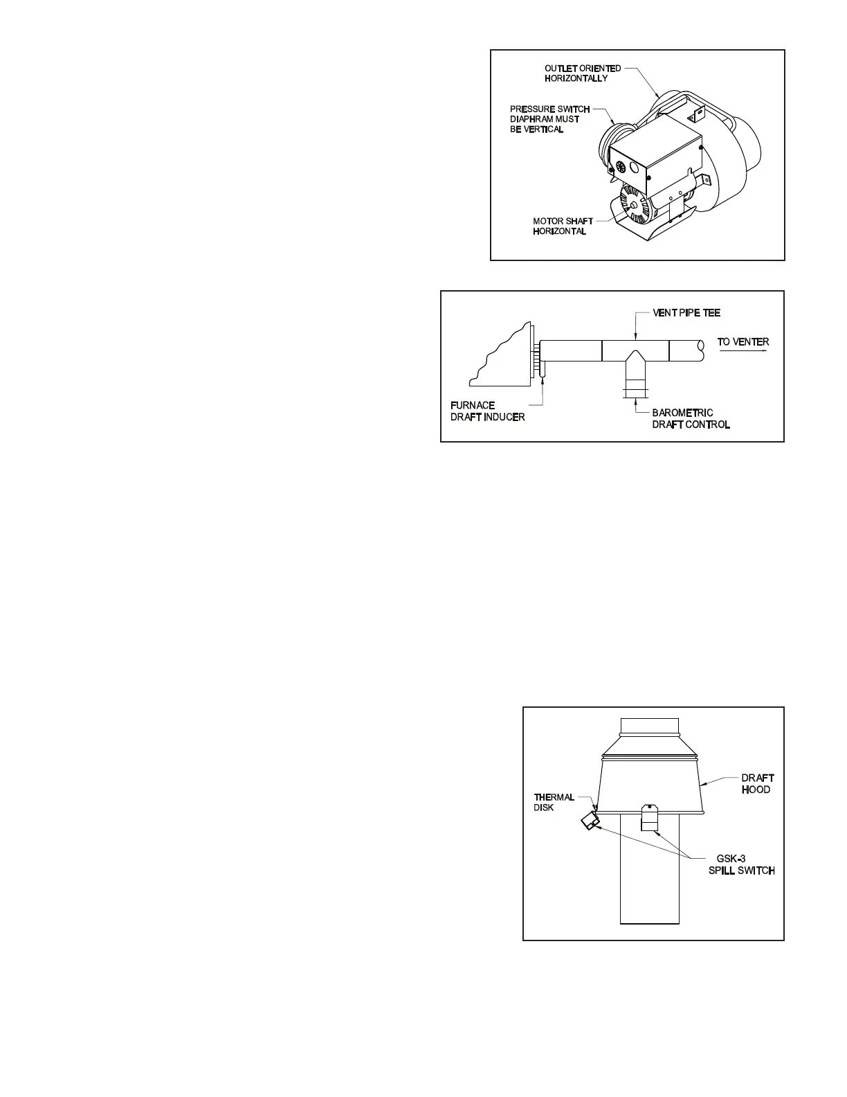
Install the power venter onto the vent hood inlet or as close
to the vent hood inlet as possible. Always install the venter
such that the motor shaft is horizontal and the pressure switch
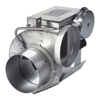
diaphragm is vertical. (See Figure 5) When venting a draft
induced gas red heating appliance a barometric draft control
must be installed on the vent system between the appliance
outlet and the venter inlet. (See Figure 6)
CAUTION: The power venter should never be installed
with the motor shaft in the vertical position. This could
allow heat to be trapped in the venter housing and radiate
through the motor possibly causing motor deterioration
and premature failure. Never attach the venter inlet directly
to the outlet of the heating appliance. Also, a minimum of
6" clearance between the venter housing and combustible
materials must be maintained.
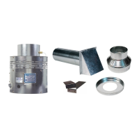
CONNECTING VENTER TO THE FLUE PIPE
NOTE: The power venter should be supported in accordance with National Fuel Gas Code Z223.1, Section 7.910
as follows: A vent connector shall be supported for the design and weight of the material employed to maintain
clearances and to prevent physical damage and separation of joints.
NOTE: For gas red heating appliances not equipped with a draft hood, a barometric draft control must be installed
between the heating appliance exhaust outlet and the power venter inlet to regulate any draft uctuations during
operation.
1. Use approved vent connectors to join the heating appliance outlet to the venter inlet securing each joint with
sheet metal screws or equivalent means of fastening when required.
2. Seal all pipe joints on the outlet side of the venter with a high temperature silicone adhesive or equivalent. Test
the vent connections for leaks by using a soap solution as recommended by the National Fuel Gas Code, ANSI
Z223.1, Section 4.1.1.
NOTE: Do not enclose the space between the plates on the
outside of the vent hood or between the inner and outer pipe of
the vent hood. This might cause overheating of the wall structure.
Local codes might require fencing around the vent hood outlet.
Figure 5
Figure 6
Figure 7
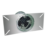
OPTIONAL GSK-3 EXHAUST GAS SPILLAGE DETECTOR
SWITCH INSTALLATION
NOTE: Installation of the GSK-3 secondary safety switch is recommended
for LP and natural gas red appliances with a draft hood. This switch
will detect exhaust gas spillage out of the draft hood due to a blocked
vent system and/or inadequate draft during operation. When this switch
senses spillage it interrupts the power supply to the gas valve which
terminates the burner operation.
1. Mount the GSK-3 on the lower edge of the draft hood with
the exposed thermal disk directed into the draft hood.
(See Figure 7)
2. Route the electrical wires along the heating appliance cabinet
within an accepted wiring enclosure in accordance with the
National Electrical Code and any applicable local codes. Keep the wires away from any HOT surfaces.
P/N 46246300 Rev M 04/20
 Loading...