page 7 of 12
GENERAL WIRING INSTRUCTIONS
CAUTION: Disconnect electrical power before wiring power venter!
Connect line voltage (110/120 VAC) through junction box access hole labeled 120 VAC ONLY. Connect low voltage
control wiring through junction box access hole labeled 24 VAC CONTROL WIRING ONLY. VENTER MUST BE GROUNDED!
Check ground circuit to make certain that venter has been properly grounded. The wiring must be protected by
an over current protection circuit such as a fuse or circuit breaker rated at 15 amperes. Prevent wiring contact with
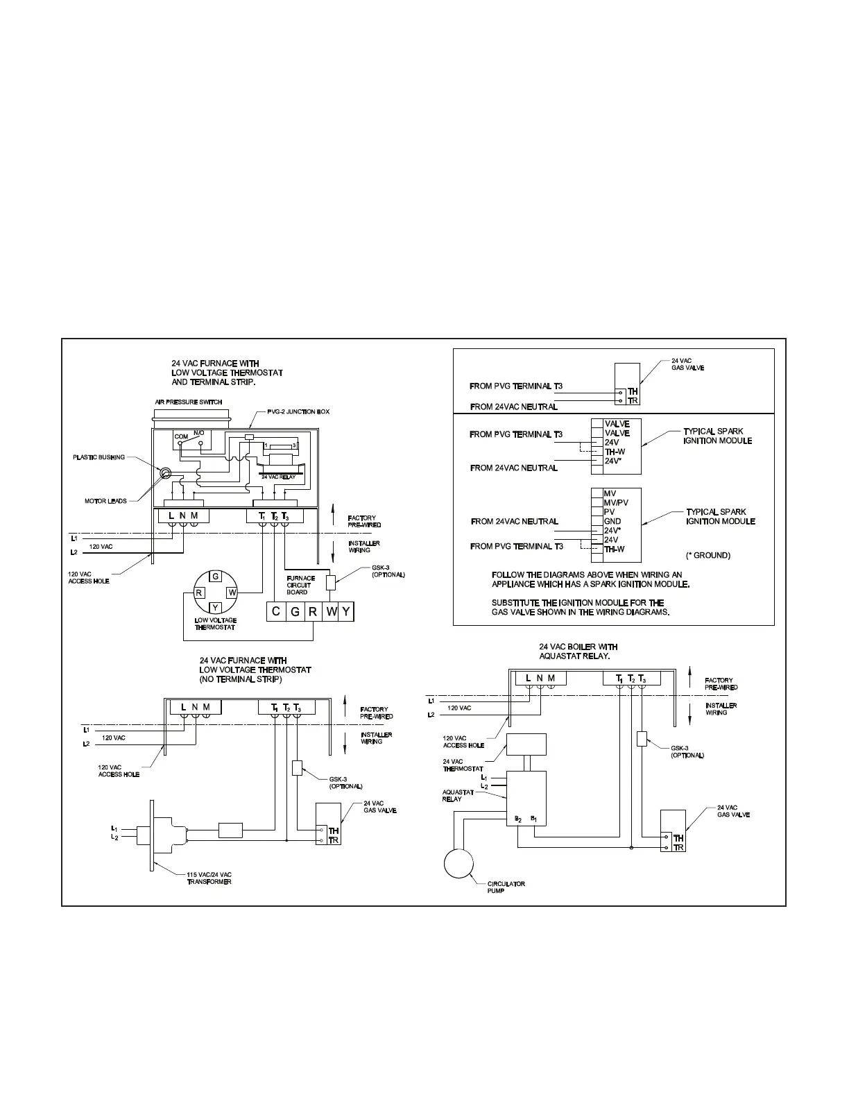
any heat source. Wire the venter in accordance with the National Electrical Code and applicable local codes. Refer to
Diagram B for proper wiring speci cations.
Diagram B
3. Wire the switch into the low voltage thermostat circuit. Refer to the appropriate wiring diagram in this manual.
4. After installation, check the amperage through the thermostat circuit and adjust the anticipator if necessary.
CAUTION: The GSK-3 is a manual reset switch. Investigate the system thoroughly for the cause of any shut down and
correct the problem before resetting the GSK-3 and restarting the system.
P/N 46246300 Rev M 04/20
 Loading...