Page 7
Page 10
User's Manual User's Manual
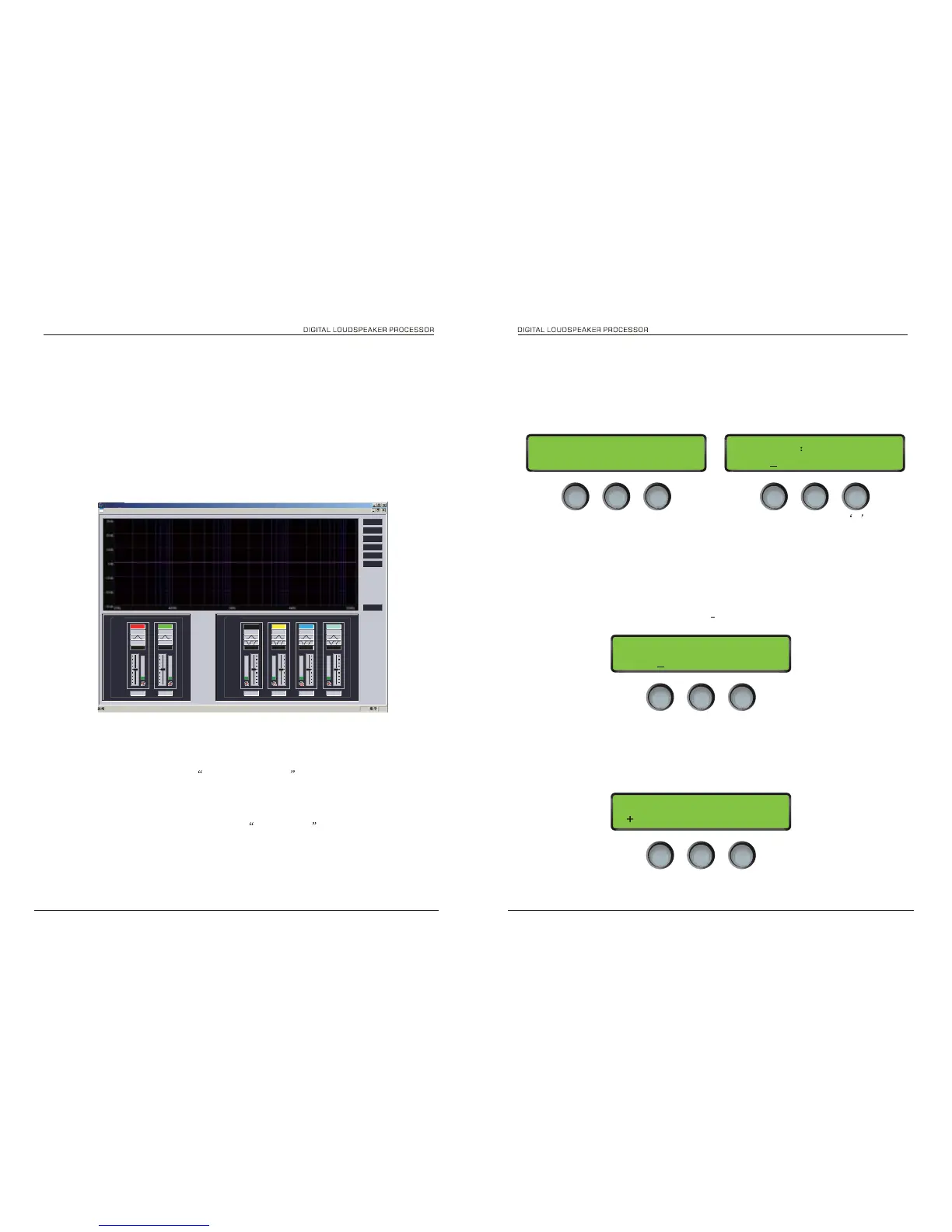
Out 1 Polarity
Normal
Out 1 Gain
0. 0dB
INPTU A EQ1
LOW-SHELF
Figure 5
5. Output Gain
The range of the control over the output gain is 36dB to +20dB in 0.1dB steps.
6. Output Polarity
The polarity (or phase) of each output may be switched individually as below.
Figure 6
program running
***
firstly please check the unit is connect to PC by USB or RS485
1. Choose connecting from menu, select comport by clicking ok,You can use
Search ID to find the connect devices also you can give the unit ID by
hand,It can save your time.
Fig 2.1
2. The Data currently use the unit will upload to Pc when they connected the
screen of unit will shows computer connecting
3. Edit program
please enter you program name , eg 2 way system and edit the output
at each channel
SOFTWARE GUIDE
Gain
- or
+
4. Input Parametric EQ
There are six bands of parameter equalisation available on every input. The behaviour of each
individual band can be changed to a variety of different filter shapes, including high and low shelves,
and bandpass. Changing the filter type is achieved by first encoder. Confirm filter type by pressing
ENTER.
Figure 4
Filter type
PEQ EQ1 20Hz
0. 0dB 0.05 / 0ct
GainFrequency
Q
DSC24 DSC24
 Loading...