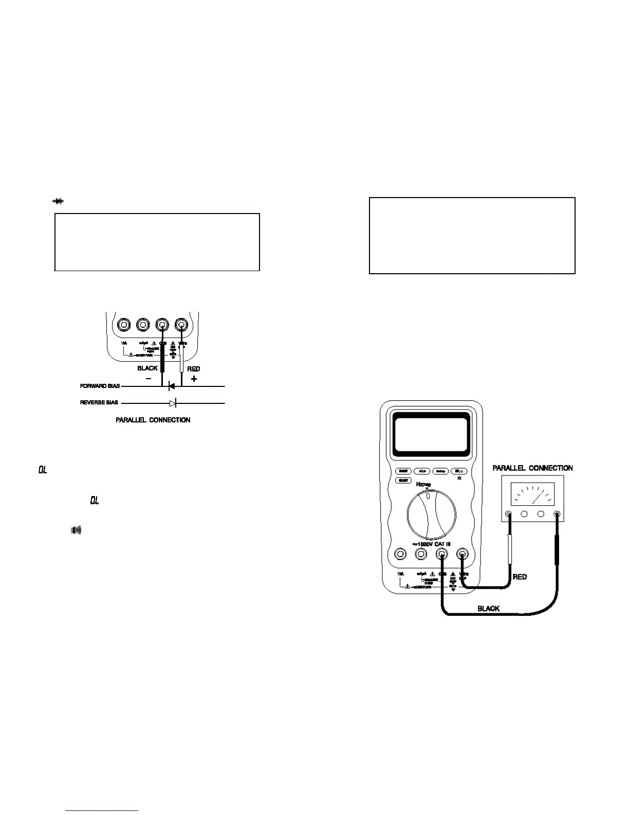
Frequency (Hz) Measurements
Frequency is
the number of cycles a signal completes each second.
The meter
measures the frequency of a vol
t
age or current signal by counting the
number
of
times
t
he signal crosses a threshold level each second.
To measure t he frequency of a vol
t
age or current signal,
press
t
he Hz/Duty
button
momen
t
arily while measuring volts or currents.
The available
f
requency ranges are 5 Hz, 50
Hz, 500 Hz
,
5 kHz, 50 kHz,
500 kHz,
5 MHz and 10
MHz.
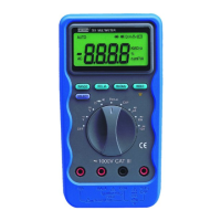
Diode ( ) Test
Use
the diode tes
t
to check diodes, transistors
,
silicon con
t
rolled rectifiers (SCRs),
and
other semic onductor dev ic es. T he
test s ends
a curr ent thr ough a
semiconductor junction, then measures the junc
t
ion’s voltage drop.
Normal
forward voltage drop (forward biased) for a good
silicon diode is between
0.4 V to 0.9 V. A reading higher than that indicates
a leaky (defective) diode. A
zero reading indicates a shorted (defective) diode.
An
indicates an open diode (defective).
Reverse
the test leads connections ( reverse
biased ) across
the diode.
The
display shows if the diode is good.
Any other readings indicate
the diode
is shorted or resis
t
ive ( defect ive )
.
Continuity
(
) Test
The continui
t
y
f
unction detects intermittent opens and shorts lasting as
little as
1
millisecond. These brief contacts cause
the meter to
emit a short
beep. This
f
unction is convenient for checking
wiring connections and
operation
of switches
.
A continuous beep tone indicates
a complete wire.
1312
Caution
Discharge all high-voltage capacitors before testing diodes.
Large value capacitors should be dis charged through an
appropriate resistance load.
Caution
Using resistance and continuity function in a live circuit will
produce false results and may damage the instrument.
In many cas es the s uspic ious components mus t
be
disconnected from the circuit
under test to obtain accurate
results.