Do you have a question about the Finn BB302 and is the answer not in the manual?
Defines TX, RX, Error, and Battery LEDs on the remote control unit.
Install new batteries, ensuring correct compartment arrangement and illumination.
Verify power, LED patterns, and switch positions; release power button if held too long.
Ensure E-Stop button is in the 'up' position; retry powering up remote.
Verify receiver power LED and 12V power at battery, switch, harness, and module plug.
Evaluate HEALTH LED for flashing green, steady, or rapid flashing indicating specific faults.
Verify keypad button illumination and CAN bus wiring for proper operation.
Analyze TX/RX light status (amber/red) for association, interference, or cable issues.
Verify remote TX/RX LEDs flash rapidly; test with a known-good remote if issues persist.
Measure supply voltage (7-28V) at receiver; inspect wiring and power sources.
Ensure proper grounding and check for radio link loss indicated by red receiver LEDs.
Verify remote TX LED response when activating functions; check for partial or full disablement.
Investigate open circuits in output channels, valve coils, or wiring for specific function failures.
Assess environmental factors like obstructions, metal objects, or interference affecting radio range.
Ensure replacement remotes are associated and have matching WS numbers for compatibility.
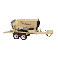
This document provides a comprehensive troubleshooting guide for the FINN Bark Blower 302 (BB302) and 5-Series (MB50) remote control system. It is designed to help users diagnose and resolve common issues with their remote control units before seeking professional service. The guide covers various aspects of the remote control and receiver, including operation lights, power-up sequences, battery checks, switch diagnostics, and communication issues.
The remote control unit is a handheld device used to operate the FINN Bark Blower and 5-Series machines. It features a series of buttons and indicator lights that provide feedback on its operational status and allow for control of various machine functions. Key buttons on the remote include:
The remote also features several operation lights:
To turn on the remote, the user must push and hold the green POWER button located on the back of the unit, then release it. The initial flashing pattern of the TX and RX LEDs is crucial for determining if the remote is properly synched with the machine. If these LEDs flash rapidly, it indicates a successful connection and readiness for operation.
The troubleshooting process begins with checking the remote's power and battery status. If no LEDs illuminate, the first step is to check and replace the batteries, paying close attention to the specific "up, down, up, down" arrangement, which is not typical. If the remote still doesn't power on after new batteries, it should be returned for service.
If the remote has power but the LEDs are flashing in a repeating pattern (TX and RX together, then Error and Battery lights together), this could indicate that the green power button was held too long, or a switch is stuck. Users are advised to release the power button and check all switches, ensuring they are in the center position and moving them up and down to free any potential sticking.
Another flashing pattern (TX and Error light together, then RX and Battery light together) points to the E-Stop button not being in the "up" position. Releasing the E-Stop by gently rotating the red button clockwise should resolve this.
Once the remote is confirmed to be transmitting a signal (TX LED flashing rapidly), the troubleshooting shifts to the receiver unit. The receiver is a separate component that communicates with the remote and controls the machine's functions. It also has several indicator LEDs:
The troubleshooting guide also addresses issues with the keypad, which is connected to the receiver. If the receiver keeps resetting, users should check if the keypad buttons flash orange when power is applied to the machine. If not, power wiring to the keypad or the keypad itself might be faulty. If the keypad buttons do flash orange, the CAN bus wiring to the keypad controller should be checked for damage.
A critical indicator on the receiver is the TX/RX LED (LED #4).
Further troubleshooting steps involve checking the supply voltage to the receiver if the remote is transmitting but not controlling the machine.
If some, but not all, machine functions are disabled, users should check if the remote's TX LED brightens when the suspected function is activated. If it does, it suggests an open circuit on one or more output channels. This requires checking wiring for broken connections, checking hydraulic valve coils for continuity (typical resistance is 25 Ohms or less), and swapping connectors from a suspected bad valve to a known good one to verify function. If the suspected output channel operates the "new" function, the valve needs replacement. If not, the output channel itself might be damaged, and the receiver should be returned for service. If the remote's TX LED does not brighten, the remote is faulty and should be returned for evaluation.
The guide also addresses "Troubleshoot Range Issue," where the radio control operates the machine but only when the operator is near. The system is designed for a typical 300 feet or greater line-of-sight operation. Line-of-sight means no obstructions between the remote and the receiver's antenna. Metal obstructions, including expanded metal or chain link fencing, can significantly degrade the signal. If range issues occur without line-of-sight, repositioning the operator or machine is recommended. If line-of-sight is maintained but range is still poor, large metal objects reflecting radio energy or other interfering radio signals could be the cause. In such cases, disassociating and reassociating the remote and receiver can help the remote scan for a better radio channel. Damage to the remote or antenna can also reduce range.
Finally, the "Replacement Remote Troubleshooting" section emphasizes that all replacement remotes must be associated with the receiver before operation. Each remote and receiver has a unique ID code that must be exchanged. It also highlights the importance of matching the "WS number" between the remote and receiver, as this number determines the project specifications and compatibility. Mismatched WS numbers can lead to incompatibility or incorrect functionality, posing a potential safety risk.
This comprehensive guide empowers users to systematically diagnose and resolve a wide array of remote control issues, promoting efficient operation and reducing downtime for their FINN Bark Blower and 5-Series machines.
| Brand | Finn |
|---|---|
| Model | BB302 |
| Category | Remote Control |
| Power Source | 2 x AAA Batteries |
| Operating Range | Up to 8 meters |
| Infrared Frequency | 38kHz |
| Connectivity Technology | Infrared |